Let’s start off with a little 3D printing vocab. An object that is 3D printed is called a thing. Where do things live? At Thingiverse.com! This website is a treasure-trove of things that other people have designed and are happy to share with you. Things range from the esoteric (yes, I have always wanted a hairy lion) to the celebration of holidays (check out these jack-o-lanterns). Most contributors to Thingiverse allow you to make, share, and adapt their design as long as you give them credit. This is similar to open source software in the sense that people are sharing their ideas for free and contributing to a community. But it gets even better. People don’t just upload their file and say have at it; they take the time to give a description, share photos, include directions, and share tips on how to get your thing printed correctly. As with most social networking sites, you can like a thing. You can also collect it into a saved folder, leave a comment, share a picture and description of the thing you made, watch it in case updates are made, remix it by making changes in some way, and share it with other users. If you are fond of many things that a user makes you can follow them.
Thingiverse was created and is run by MakerBot. There are currently over 739,050 3D models on Thingiverse along with over half a million users. These users range from novices who are just getting started to professionals. You can find simple designs as well as quite complex designs, and everything in between. Almost anything I have thought of printing I have been able to find on Thingiverse. It is user driven so you may come across the occasional design that doesn’t print correctly, but it is also self-correcting in the sense that if this happens other users will comment to let you know.
Now that you are familiar with Thingiverse, you might wonder how this website can be used in a classroom. Maybe your students are just getting started with 3D design and aren’t capable of designing some complex thing, but they may be capable of taking an existing design and remixing it or adding to it. Let me give you an example. One of the activities I designed involves cryptography. I had the idea to use a decoder ring but at the time I was fairly new to 3D design and didn’t have the skills to make the ring spin. I did a quick search on Thingiverse and, sure enough, I found someone had posted a decoder ring. Rather than trying to start from scratch to design a ring, I knew it would be much easier to take this really great ring that somebody else had designed and put my own twist (no pun intended…okay, maybe a little pun intended) on it. I didn’t really need to modify this ring so instead I designed a viewer that would attach to the ring and make it clearer which two letters match up when encoding or decoding a message See here for a full description of this activity.
Let’s assume that you already have your design done. It can be a file you downloaded from Thingiverse or one you created yourself. The first thing you’ll want to know is what type of file a 3D printer uses. The most common file is an STL file, which stands for Standard Tessellation Language. Whatever software you use to create your 3D object treats your object as a whole piece. But this is not how a 3D printer prints. If you have ever had the pleasure of watching a 3D printer in action (it’s kind of meditative) then you’ll know that it prints layer by layer. So when you save your design as an STL file it approximates the surface of your object using triangles.
I am going to share how to get your file set up and printed on a MakerBot printer because that is the type that I own and it is a popular brand. MakerBot helped make 3D printing a household name. In fact, in 2016 TIME magazine named the MakerBot Replicator the 49th most influential gadget of all time because it is “the model that made the technology widely accessible for the first time, thanks to its sub-$2,000 price tag”. Before you can use the printer you will need to have MakerBot Desktop installed on your computer. Once MakerBot Desktop is open you can click “ADD FILE” to open your STL file. You will see it displayed on a mock printing platform. Holding the left mouse button, you can move the object around to see how it looks from different views. On the left toolbar click the double arrow button and then click “on platform” and “center” to make sure your object is (you guessed it) on the platform and centered.
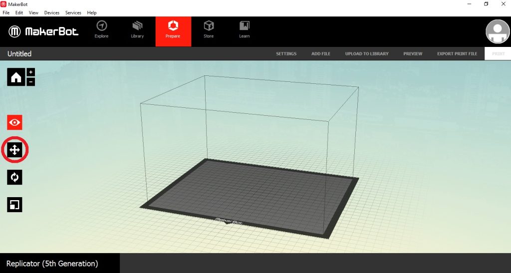
It is especially important that your object be on the platform because otherwise it will not print correctly. Unfortunately, the printer cannot print an object floating in the air; gravity just doesn’t work like that. If you would like to print more than one object at a time you can add additional files. You can use some of the other buttons if you want to scale or rotate your object. You may also want to look at the settings. See this picture for the options.
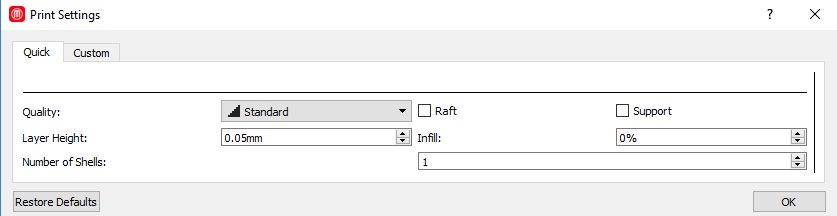
From here you can set the quality: Low, standard, or high. Layer height is preset to .2 mm. This is the height that each layer of filament will come out. You can get better detail if you lower this value, but it will take longer to print. Another option is the infill. This is preset to 10%. Infill measures how dense you want your object. The 3D printer doesn’t completely fill in your object; rather, it creates a pattern using a shape. You can change the shape but the default is hexagonal. The higher infill percent, the more hexagons it will make and this will make the object sturdier. Of course, this will also increase print time. A neat visual to see how different infills look can be seen here. The next option is number of shells. This is preset to 2. The shells are the outline of the shape. Increasing the number of shells will increase the strength. A good visual to see how the number of shells works can be seen here. There are also checkboxes to include rafts and supports. Rafts are used to give your object a foundation. Here is a picture of an object with the rafts.
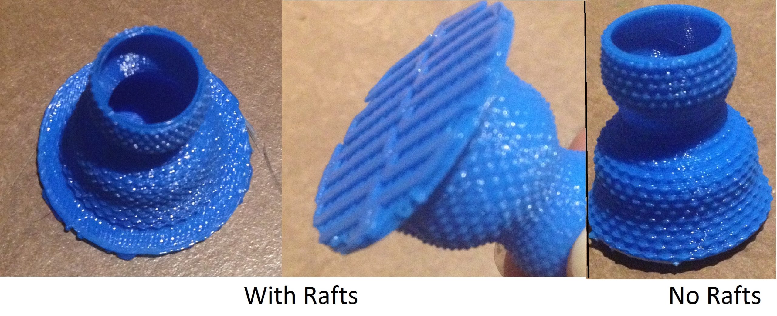
Once it is done printing you can easily (for the most part) pull it off of your object. I have found that I usually do need to include rafts because the times I have tried not to have resulted in the object not printing correctly; it kind of forms one big pile. Depending on how your object is shaped will determine if you need supports or not. You always can print supports, but if your object doesn’t really need them it will just create unnecessary vertical lines that you have to remove, and it is not always easy to remove the supports. Anytime you have an object with the first layer starting somewhere other than the bottom you will need supports. Think of the letter ‘T’. The top line doesn’t have enough support from the vertical line to print without supports. Once you are satisfied click “preview” on the top toolbar. The preview will show you what the printed object will look like and tell you how long it will take to print it. If all looks good you can save the file to your USB drive. It will save as .makerbot file. This is the type of file your printer can read. In addition to the object itself, this file type includes directions on how to print, such as all those settings we just looked at.
Now that you have your file all ready to print you can bring it over to your printer and insert it into the USB slot. Now I will take a step back to go over setting up the printer. On a regular printer you know that you need to provide ink. On a 3D printer this “ink” is called filament. Filament is a plastic material that looks like a string and comes wrapped on a spool. Look at this picture to get a better idea.
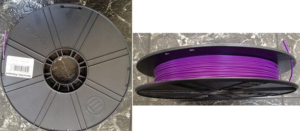
I own a MakerBot Replicator printer and this type of printer uses a filament called PLA (Polylactic Acid). Interestingly enough, PLA is made from cornstarch. You may have heard some concerns about printing in an enclosed space. A study was done to test various printers and types of filaments. They found that PLA filament was the safest; it only emits a substance called lactide, which is non-toxic. The filament comes in many colors, including translucent and glow in the dark options. You will need to load the filament. It comes wrapped around on a spool. Insert the spool and thread the end through the small white pipeline. Keep pushing it through until you see it popping out the other end. On the main menu go to “Filament” and then “Load Filament.” You have to wait a few minutes for the extruder to heat up. The extruder is where you will load the filament into. It will heat the filament up and push it through a nozzle onto the platform to form your object. You’ll be prompted to insert the filament and press the round button when you see the filament coming through. Voila, your filament is ready.
I know the printers look very intimidating, but they are actually quite simple to use. Once your USB drive is inserted, click on print, then USB Storage. Spin the circle until you find the file you want to print and click on that. Now comes the boring part; you have to wait for your object to print. OK, you don’t literally have to wait around. You can leave it to print. Or you might act like I do and come back every five minutes to check on the progress bar that tells you what percent is done. You will already know the time estimate for your print, but just so that you’re prepared, they do take a long time. Eventually your print will finish. Once the platform is lowered you can slide it out to remove your object. Sometimes it will pull off easily, but sometimes it sticks to the platform. For these instances you may want a 3D print removal tool. Yeah, they actually make those. See here. If you used rafts you will want to pull those off and then you have your 3D printed object. To quote my three year old nephew Grayson, it is “easy as pie.”
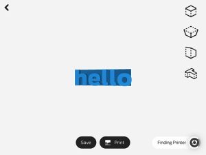
Now we can get started with 3D design. The first method I will show you requires little to no skills in design. The method I will discuss here uses an app called MakerBot PrintShop. Right now this app is only available for iPads. This app is extremely easy to use. There are six kinds of designs you can make. The first one is called Type Maker. Here you can type letters or words and have them pop up. There are options to change the height of your letters, change the length of your letters, and change the angle of your letters. All of these options are easily controlled by a slide bar.
Next is Bracelet Maker. Here you can change the width and diameter of your bracelet, design ridges on the outside, and include a break in the bracelet.
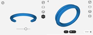
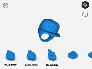
With Ring Maker you can change the size of the band and make the ring various shapes, such as an owl or hat. There are some ring options with characters such as Hello Kitty that you would have to pay 99 cents to print.
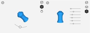
Next is Vase Maker. Here you can control the height and design on the outside, and there are six points where you can change the width.
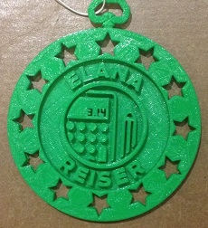
Next is Medal Maker. Here you can pick a design for the outer part of the medal as well as the inner part and you can type in between the two designs. I designed a medal for the presenters at a math conference we held at my school.
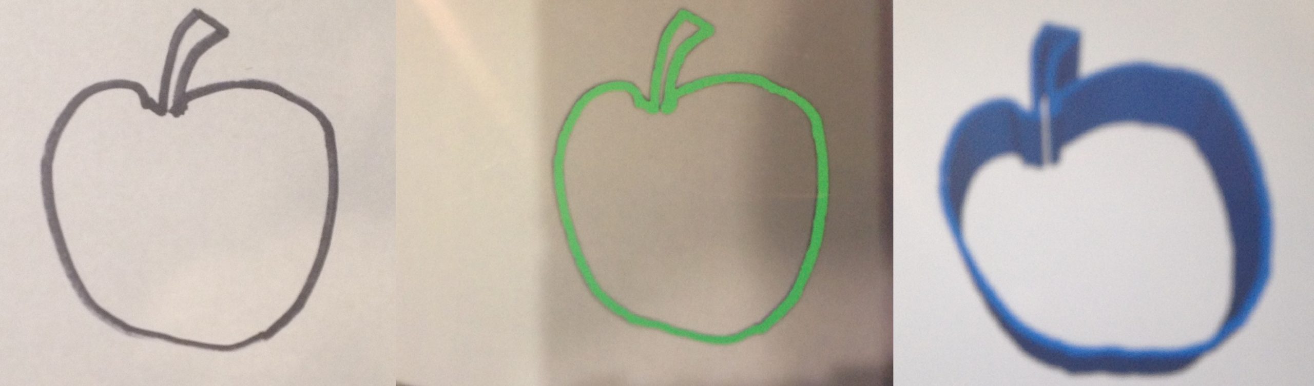
The last one is called Shape Maker. This is the one where you can be the most creative. First you would draw a picture. It’s best to use a dark black marker and don’t make any stray marks or they will also be part of the object. You also have to be careful about leaving holes. For example, if you draw a smiley face then you will actually get the circle and facial components each as separate pieces (which is fine if that is what you want). I wouldn’t use this tool for an elaborate drawing, but it is good if you just want the outline of an object. Then in the app you use the camera to take a picture. You will see your drawing gone over in green. This is what the app will add height to in order to make it three dimensions. This process is called extruding. There is a slider you can use to make it not pick up lighter lines. To show you how it works I drew an apple and then used PrintShop to turn it into a 3D object.
Once you have a design you like using any of these six tools you can save it to your MakerBot account. If you installed MakerBot Desktop you will already have an account. To print you can open MakerBot Desktop and at the very top you will see your library folder. Click on that and open the design you want to print. From here the process is the same as discussed earlier.
I did use PrintShop to make models for one of my lessons on logic/problem solving. This activity comes from the book Harry Potter and the Sorcerer’s Stone. Harry and Hermione are in a room where exits are blocked by fire. Seven bottles are on table in the room, along with a piece of paper with the following poem:
Danger lies before you, while safety lies behind,
Two of us will help you, whichever you would find,
One among us seven will let you move ahead,
Another will transport the drinker back instead,
Two among our number hold only nettle wine,
Three of us are killers, waiting hidden in line.
Choose, unless you wish to stay here forevermore,
To help you in your choice, we give you these clues four:
First, however slyly the poison tries to hide
You will always find some on nettle wine’s left side;
Second, different are those who stand at either end,
But if you would move onward, neither is your friend;
Third, as you see clearly, all are different size,
Neither dwarf nor giant holds death in their insides;
Fourth, the second left and second on the right
Are twins once you taste them, though different at first sight
(Rowling, 1998, p. 285).
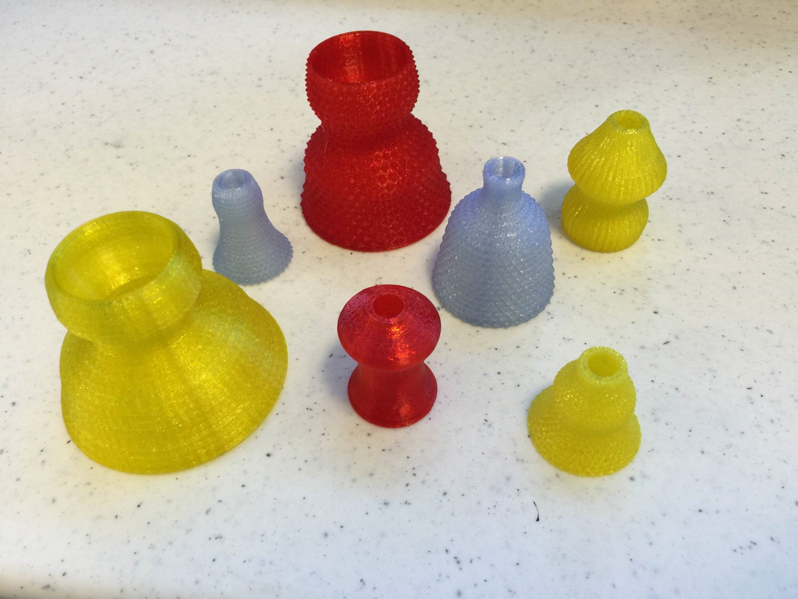
Hermione realizes that she can use logic to find the right bottle rather than relying on magic. She figures out the correct bottle and they move forward. However, the book doesn’t give a picture of the bottles so it is not possible to fully solve this riddle. In this activity students are asked to use seven bottles of different sizes along with the clues to set the bottles up in a way that there is only one possible solution. To design the bottles I used the Vase Maker in PrintShop. I designed seven vases that all looked different and were of differing heights. I saved them to my library and then opened them in MakerBot Desktop. Now, for this activity I didn’t really want vases. I wanted bottles. Therefore, I used the scaling option to shrink them all. My bottles came out looking like this.
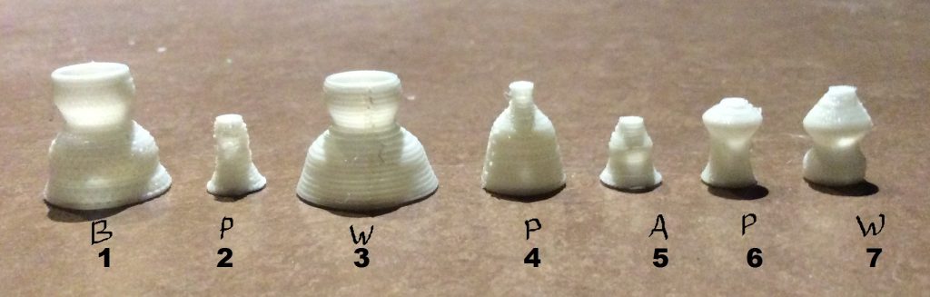
If your school has a set of iPads you could let the students design their own bottles. We do not so I just printed multiple sets to give one to each group. Students then had to set up the bottles in order to solve the riddle. You can make this activity a little easier by showing them an order for the bottles and then ask them to solve the riddle.
From the riddle we know there are seven bottles with one that moves ahead (A), one that moves backward (B), two that are wine (W), and three that are poison (P). The second clue tells us that the two ends are different and neither of them is A. We know from the first clue that P is always to the left of W, so the left end cannot be W. Largest (1) and smallest (5) are not P. The only possibility left for 1 is B. Since 2 and 6 are the same, they therefore cannot be B or A because there is only one of these. They must both be P because if 2 is W then 1 would have to be P and we already know it is B. This means 3 and 7 must be W. The remaining 4 must be P and 5 must be A. The order becomes BPWPAPW.
There are many ways to arrange the bottles. The best way to guarantee a single solution is to put the largest and smallest bottles in positions you don’t know much else about (like 4 or 5) or where not being poison is helpful, like 1.
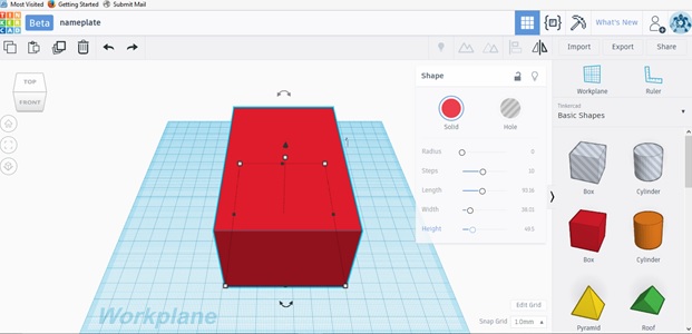
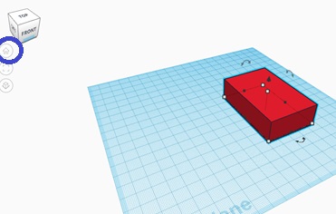
Now we can finally get to some real designing. TinkerCad is a free web-based program. This means you don’t have to download it, which means you don’t have to worry about someone from IT getting it on your computers, and you don’t have to worry about having a license for it. It just makes life easy! What I love about TinkerCad is how user friendly it is and how easy it is to get started. First, you will have to go to tinkercad.com and create an account to start using it. When you first login they will give you a tutorial to learn a little about the program. You can choose to go through that or you can just get right to the program and tinker around. I created a tutorial for teaching students some of the features that I will go through now. If you are a new user you may want to follow along. I have students design a nameplate necklace because it makes the item personal and through its creation we go through many design tools that they will want to use. First, click on “create new design.” You will notice in the top left that TinkerCad automatically assigns a name to your project. That is because the program will automatically save it. But the name generated will be silly sounding. The one I just opened is called ‘Fantastic Jofo.’ You’ll want to rename it something meaningful to your design. You can click on the name and type in something like ‘nameplate.’ Next, we want to get the bottom rectangle where your name will sit on. You will notice on the right there are different objects you can choose from such as shapes and letters. First, click on the red box and drag it over to your work plane. If you have the box selected you will see a menu that controls length, width, and height. You can use those slidebars to change the dimensions.
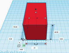
Another option is to use the small squares at the corners. And a third option is to drag the ruler that you see at the top right near your object. The dimensions will be displayed and you can click on one of the numbers and type in a new dimension.
If you want to move your object to a different spot on the work plane, you can left click and drag it in an x or y direction. To move it up or down you click on the black arrow on top of the object.
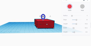
To rotate your object use the double arrows. To change your view you can right click and spin your object around or you can use the cube in the top left.
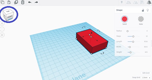
If you ever get disoriented or want to return to the original view just click the home button on the left.
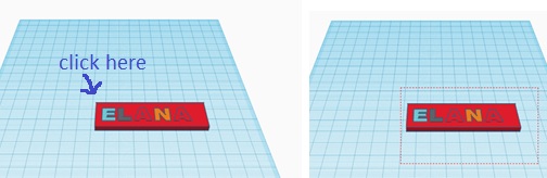
To zoom in or out you can use the scroll on your mouse. Now that we have all the basics down, let’s get back to our nameplate. Give your box the dimensions length 80, width 22, and height 4. The easiest way to get exact dimensions will be using the ruler. If you have a long name you may want to increase the length. Next, pick the letters of your name from the right and place them on the box. If you click on the arrow you will get a dropdown menu. Click on ‘text.’ You may want to resize the letters or if you want them to pop up higher you can raise them. Once your letters are on, you want to make sure they line up correctly. The easiest way to select all your letters is to select everything by left-clicking outside the object and then dragging the box you see to go over the whole object.
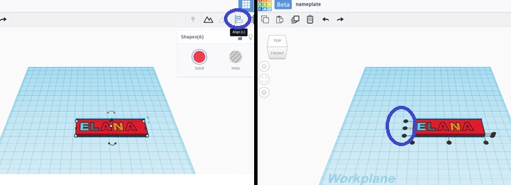
To unselect the rectangle you can hold shift and click on it. Now you will have all the letters selected. To align them you can click ‘align’ on the top toolbar. It looks like a vertical line with two different shaped rectangles. You will see a bunch of dots appear. You can click on any of the three dots on the left. This will align the letters by top, middle, or bottom. In this case the letters are the same length so it doesn’t matter which you choose. But if you ever make a mistake there’s always the undo button.
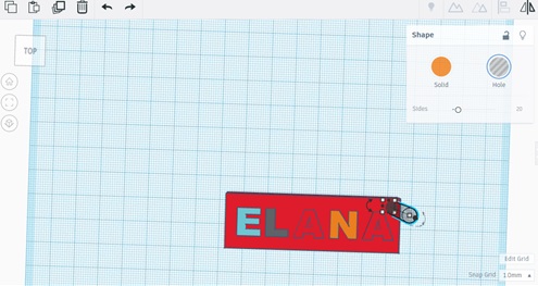
Next we are going to put holes in to put the necklace on. You can put them on the sides or on top. Go back to basic shapes on the dropdown menu and place a cylinder hole on your work plane. It will come out too big so you will need to change the size so that it fits on your nameplate. I gave mine a radius of 5. You will have to change the length and width. If you want to keep it a circle make them the same value or you can turn it into an ellipse. It just depends on how you want your hole to look. I then dragged it to the top right corner of my nameplate. If you want to use very small movements you can also use the arrows on your keyboard to move it around. You’ll see later that the height doesn’t really matter because we are just using this to create a hole. I’ll also point out that you can make any shape into a hole. When you put the box on the work plane and saw the options to change the dimensions you may have also noticed the solid circle was highlighted. If you clicked on ‘hole’ it would turn the object into a hole.
Now, I want to get another hole on the other side of my nameplate. Rather than repeating that process it will be easier to duplicate your existing hole. You can click ‘duplicate’ on the top left. It looks like stacked squares. Your duplicate will be right on top of your first cylinder. Just left click and drag it to the other side. You want the full cylinder to be on your nameplate so don’t be afraid to change your view around if you can’t see. Next, we want to align the cylinders. Repeat the same steps we did when aligning the letters. To select them I clicked on one then held shift to also select the other. Once they are aligned you want to actually create the holes. Start by selecting everything like I showed you earlier. Then click the ‘group’ button on the top right. It looks like two triangles joined together. This will combine all the pieces together into a single object. You will see the holes are created and the letters are joined to the rectangle. Now, if you move the rectangle everything else comes with it, whereas before if you moved the rectangle only the rectangle would move.
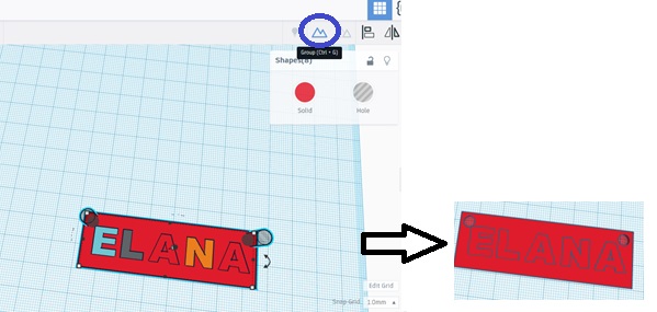
If you made a mistake or want to change something you can always ungroup. That is just the button with triangles next to ‘group.’ Now our design is done. Don’t worry about the color of it because color will be determined by what color filament you use in the printer. Throughout the whole process it has been automatically saving to your TinkerCad account so if you ever want to view it another time you will see it in your designs. To export it to be able to print you can click ‘export’ on the top right. You will see the option to take everything or just select a part of the design. We only have one object now but in other designs you may have multiple objects and for some reason only want to print one of them. Then click on STL and it will automatically save to your computer.
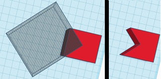
I will share one other useful design tip that we didn’t cover in the nameplate. If you want to create a new shape out of an old shape you can cut off pieces by putting a hole on top and combining the objects. Here is an example where I combined two boxes to get a new object. This is not an ideal way to create shapes.
You might get frustrated and ask why you can’t just draw a line. Well, Tinkercad doesn’t work like that because it is really made for its simple design and ability to use the program without much training. But the good news is there are other programs that will allow you to draw objects and we will discuss one of those next!
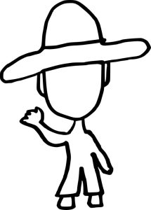
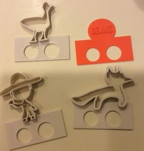
Lastly, I want to discuss another way to extrude a drawing to turn it 3D. I discussed one method earlier using PrintShop. Another method is to draw a picture and scan it so that you have a digital image or use some kind of software to draw a digital image. In this logic activity I wanted to create a fox, a goose, a bag of beans, and a farmer for students to act out a famous logic riddle. First I drew them out and scanned them. This is what the farmer looked like.
Then I converted the image to a SVG (scalable vector graphics) file. Most images are composed of pixels. If you zoom in really close it tends to look blurry. An SVG file does not have pixels so that if you make it bigger the object is preserved. You can find free converters such as this one where you upload the scanned image and then download the SVG file of it. This type of file is still two dimensions. In TinkerCad you can open an SVG file. Just click on ‘import’ and then open the file. I have found that they usually come out pretty large so I scale it to 25%. You can see it is the same picture but extruded to become three dimensions.
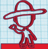
This is what my objects looked like when printed.
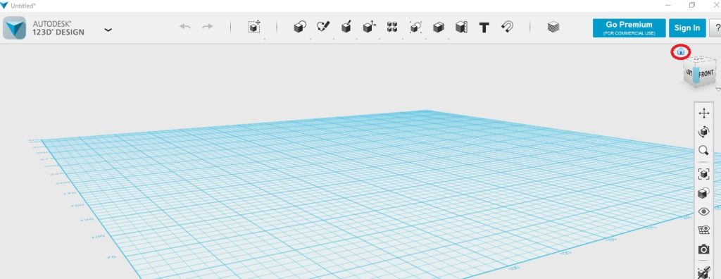
The next design software I will share with you is called 123D Design. Think of it as one step up from TinkerCad. There is a bit of a learning curve but you can do a lot more with it. You will have to download this program, but it is also free to use. It is available here. When you load the program you will see the work plane just like we saw in TinkerCad. You will also be able to zoom in and out with the mouse scrollbar and be able to change your view by right clicking and holding down. You will see the same home button you can push to return to the home view; it’s just on the right side this time. The cube under it can be used to get various other views.
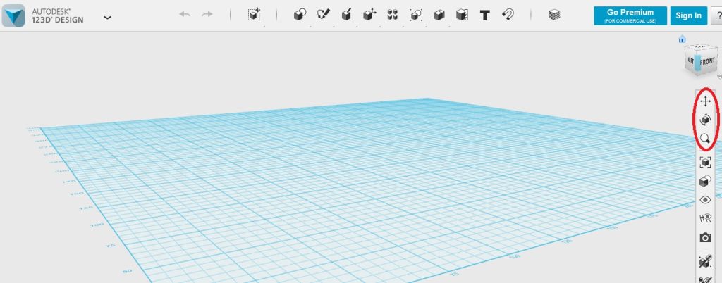
You can also use the top three buttons on the right toolbar to change your view. The double arrow will pan, which allows you to move side to side or up and down. The second one orbits, which is exactly what a right mouse click will do. And the third one zooms.
This program looks pretty intimidating and it did take me awhile to work up the courage to try it. I will walk you through some examples on getting started with 123D Design, but keep in mind it has many other capabilities. If you do a quick search on YouTube you should be able to find a tutorial on any of the features that we did not go over. What led me to learning this program is that I was working on a calculus activity to show the resulting object when a region is rotated around a line. This is beyond the capability of TinkerCad, so I had to step it up. You will see this activity discussed in full later on in Chapter 5, but for now I will show you how I used 123D Design to achieve this rotation. I chose to look at the region bounded by y=2x2-x3 and y = 0 between x = 0 and x = 6. First, I got the 2 dimensional graph of y=2x2-x3 using desmos.com. Then I did a print screen to capture the graph.
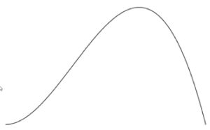
I wanted to get this image as an SVG file so I used the converter as described earlier and then opened it in 123D Design. The next step was to get this to be an enclosed region so that I could rotate it. To do this I used a tool called Polyline. You click on the sketch button (circled below, it looks like a pencil that is sketching) and then Polyline is the first curvy button.
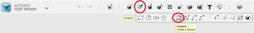
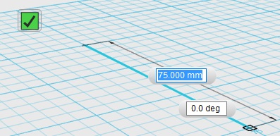
This tool is used to draw a line or polygon. You click where you want the first point to go and then keep clicking where you want additional points. You will also notice that you can set the length and/or degree if you have a specific measurement in mind. Once you are done you click on the check mark that appears to exit out of Polyline mode.
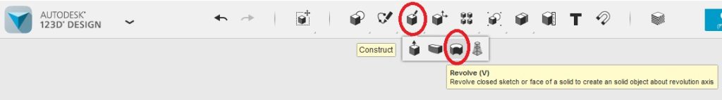
Then I used Polyline again to draw a line acting as the x axis that this shape would get rotated over. Next, I wanted to break the region up into rectangles. To do this I again clicked the sketch button and then clicked on the first button to sketch a rectangle. To use this tool you first click on where you want to place the rectangle. The software guides you through the steps. You can see it first says “Click on grid, sketch or solid face to start sketching.” Next, you click where you want the first corner of the rectangle to go. Next, you will draw the rectangle. You can either move the mouse to give it a length and width or you can type values into the size boxes. When you are satisfied with the size just click one last time and then you got a rectangle. Then click the check mark to exit this mode. I did this many times to create rectangles to fill my region. Then I wanted to revolve each rectangle over the x-axis. To accomplish this I used the revolve tool. This can be found by clicking the Construct button (which looks like a cube with a pencil on top) and then the third one in is Revolve.
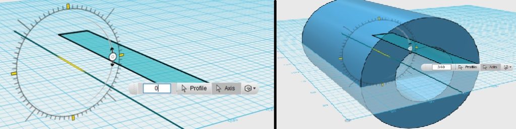
Once you click on ‘Revolve’ you will see a menu pop up that says ‘profile’ and ‘axis.’ I clicked on profile first. This is the object that you want to rotate. In this example I clicked on the rectangle so that I can rotate it over the line. Next, I clicked on axis. This is what line you want to rotate over. I clicked on the line I have. Then you will see that it asks how many degrees you want to rotate. I want it to go all the way around so I typed in 360.
Going back to my graph, I rotated each of the rectangles and came up with this image.

I’ll show you a few more things you can do in the program. If you select an object you will see a gear box appear. Click on that and a new toolbar appears. You will find all of these same tools on the top, but this is another way to access them. The first one is to move your object. Clicking on it will make arrows and a number box appear.
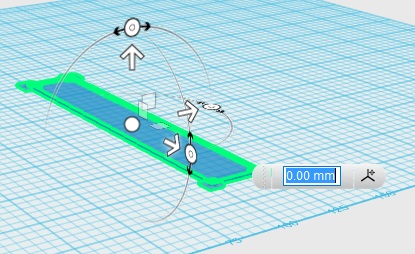
You can choose which direction to move your object. It moves along the x, y, or z axis. You can click the arrow and drag it with your mouse or put the numerical value you want to move in the box. If you type in a negative number it will move in the opposite direction. Clicking on any of the three circles allows you to rotate your object. Hit enter once you have moved in all the directions you would like. The next button is to scale your object. You can see a box appear that asks what factor you wish to scale. Type that in and then click outside of the box for the scaling to occur and to exit that tool. The third button is to extrude your two dimensional object. I clicked the extrude button and then it asks me to select which object I would like to extrude. I clicked on the rectangle and when the text box appeared I typed in 10 mm. You can see the new three dimensional box I got as a result.
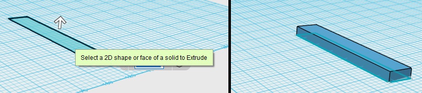
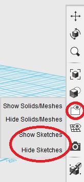
You will notice that the original rectangle is still visible under the box. If you ever don’t want to see the original two dimensional object you can make it invisible by clicking the eye with a white box icon on the menu on the right. You will see the option to show or hide sketches.
As I said earlier, there are many other functions that this program can perform, but what I showed you here are all of the basics. Once you get some familiarity with using them you can play around with some of the others. I hope you can see that even though this program does take a bit of time and practice to learn, it is much more powerful than TinkerCad and it’s worth it!
Reference
Rowling, J.K. (1998). Harry Potter and the sorceror’s stone. New York: Scholastic.
