23 Outcome 3: Measuring and Testing Instruments
Section Information
Outcome/Competency: You will be able to use measuring and testing instruments.
Timing: 1h15m
Rationale:
Why is it important for you to learn this skill?
Measurement and testing equipment are an integral part of the powerline technician’s toolkit. These instruments are used to take accurate measurements, test for voltage or current, measure resistance, and perform many other functions. Without these instruments, the technician has no way of knowing if they are working in a safe environment or if proper voltage is being supplied to the customer.
Objectives:
To be competent in this area, the individual must be able to:
- Identify and describe the basic operating principles of electrical measuring devices
- Identify series and parallel connections
Learning Goals
- Distinguish between series and parallel connections
- Describe the application of different testing instruments
Introduction:
In this section you will learn about series and parallel connections, as well as how to use measuring devices such as ammeters, voltmeters, ohmmeters, and wattmeters. You will be presented with concepts and then given opportunities to see or test these devices. You will then test your understanding with some short review exercises.
Instructions:
This outcome is covered in the trade science course. As such, this objective can be used as a review, or omitted if time is short.
- Cover the following content in each topic as a group (either reading out loud or independently) then give an opportunity to answer any questions.
- As you discuss each tool, give students an opportunity to hold the tool. Where possible, demonstrate how the tool is used. Ensure all proper PPE is used and safety should always come first.
- Have students do the review questions independently, then take up answers.
Topic: Series and Parallel Connections (5m)
To use electrical meters properly and safely, we must know the difference between series and parallel connections.
A series connection is a connection that has only one path for current to flow. So, a meter hooked in series must therefore be hooked “directly in line.”
A parallel connection is a connection that creates an alternate path for current to flow. This is basically a series connection with a jumper around it. A jumper or alternate path will always prevent a series connection.
As you will see, it is very important to know which meters are hooked in series and which are connected in parallel.
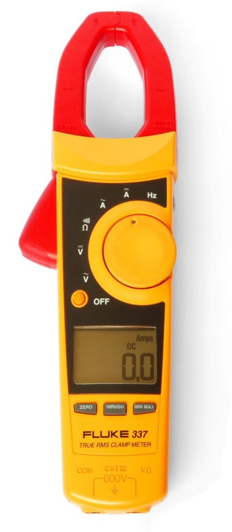
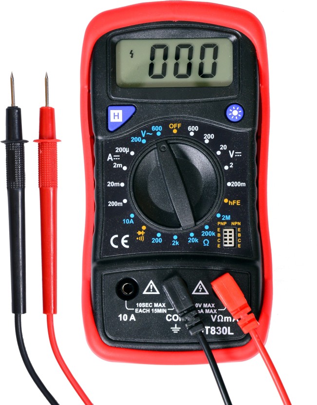
Topic: Electric Measuring Devices (40m)
 |
 |
Ammeter
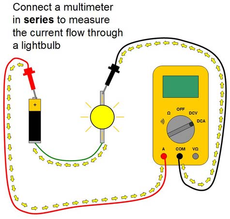
An ammeter measures current in amperes (A) and must be hooked in series.
As you can see, the flow of electricity has no choice but to flow through the ammeter. Because of this, an ammeter must have very low resistance (0.01 ohms is typical.) A high resistance would affect the amperage of the circuit.
For example:
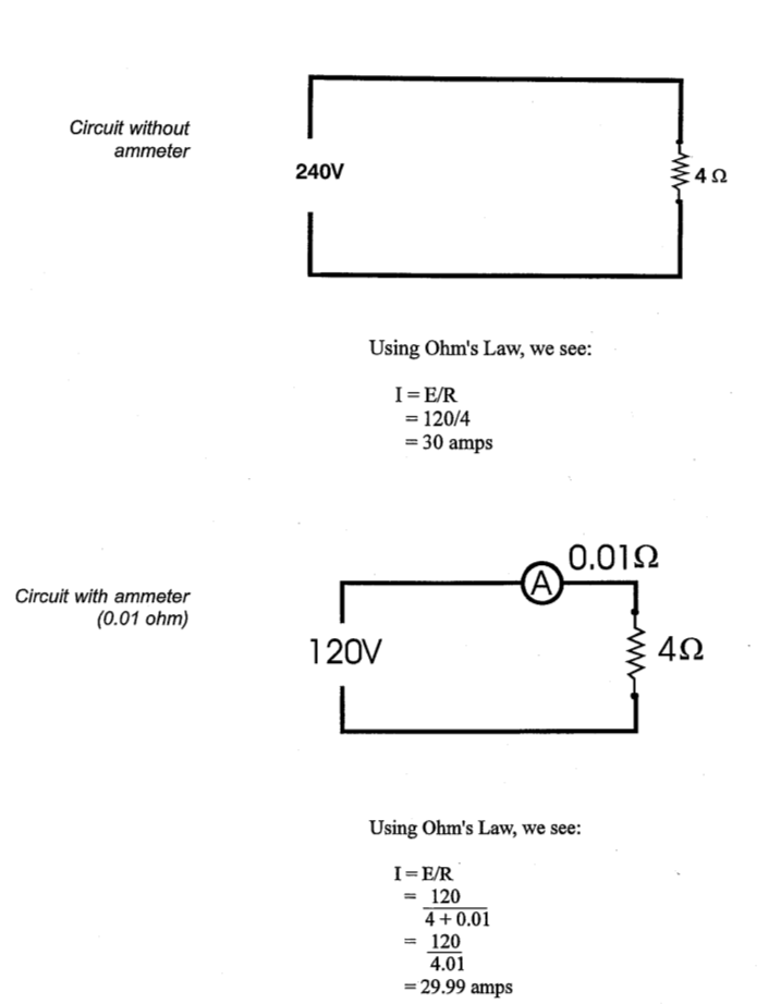
As you can see, there is very little effect on the circuit. You can also see that a high resistance would affect the circuit so much that the measurement would be inaccurate.

Always start on the highest scale and work down to obtain maximum accuracy without damaging the meter. This should not be done while the meter is on an energized circuit.

If an ammeter is connected in parallel accidentally, it’s low resistance will allow almost all the current to flow through it, resulting in a destroyed ammeter and flash burns.
Voltmeter
A voltmeter measures voltage (V) or potential difference between two points and must be hooked up in parallel (directly across the source of power.)
Since it is hooked up in parallel, we can draw the conclusion that, unlike an ammeter, its resistance must be very high. Since we know current flows easier through a low resistance than a high resistance, it is safe to say almost all the current will flow through the other circuits.
Also, a voltmeter cannot be connected in series because its high resistance would make it virtually impossible for any electrons to flow.
Ohmmeter
An ohmmeter measures resistance (ohms) and has its own power source. An ohmmeter can be tested quickly before use:
- Leads held together will simulate a short circuit or a circuit with very low resistance. The resistance should be very close to zero (0).
- Leads held apart will simulate infinite resistance. Air is an excellent insulator, so no current will flow. This open circuit will read as infinite (1) or overload (OL).
Never put an ohmmeter on a live circuit.
Wattmeter
A wattmeter measures watts (W), which is the product of voltage and current (E x I).
Watts can be calculated with voltmeter and ammeter readings. This is done in some instances, but it is easier to use a wattmeter.
A normal house meter is a variation of the wattmeter.
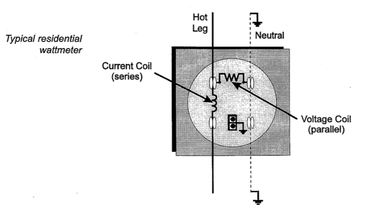

House meters should be handled with care to prevent damage and inaccurate readings.
Review Exercises: Measuring and Testing Instruments (30m)
- ( T / F ) A series connection will result in one path only.
- A voltmeter is hooked in ( series / parallel ) while an ammeter is hooked in (series / parallel ).
- A parallel connection will result in a circuit with:
- One path at most
- Two paths at least
- No paths at all
- None of the above.
- ( T / F ) An ammeter and voltmeter can be used to measure watts instead of a wattmeter.
- Connecting an ammeter in parallel will:
- Give you the correct reading
- Allow dangerously high amperage to flow through it
- Give a voltage reading
- None of the above
- ( T / F ) To prevent damage to meters, start on the lowest scale possible and work up.
- ( T / F ) A voltmeter has a low resistance to allow all the amps to flow through it.
- ( T / F ) Ohmmeters may be hooked on live lines only.
Answer Key
- True
- Parallel / Series
- B
- True
- B
- False
- False
- False
