50 Outcome 5: AC and DC Circuits
Outcome/Competency: You will be able to solve equations and scenarios related to AC and DC circuits
Rationale:
Why is it important for you to learn this skill?
Calculating three properties of electricity (voltage, resistance, and current) is central to this objective, and to your understanding of electrical flow in powerlines. A powerline connecting a power station to the customer is essentially a large circuit. You will need to measure the properties of electricity on your job; and being able to calculate voltage, resistance, and current will tell you if there are any faults.
Objectives:
To be competent in this area, the individual must be able to:
- Distinguish between series and parallel circuits
- Describe the application of electrical measuring instruments
- Describe the nature of alternating and direct current
- Calculate Voltage, Resistance and Current in direct current series and parallel circuits
Introduction:
This module will cover basic circuit components and terms, the application of electrical measuring instruments and how to interpret their readings, how electrical laws can be applied to calculations for parallel and series circuits, and how to distinguish between alternating and direct currents. This section will include class discussions, articles to be reviewed, review questions, and a cumulative test.
Topic 1: Series and Parallel Circuits
A circuit is a closed loop path for electrons to flow. Electrons can flow easily through metals, so a circuit is generally made of copper of aluminum wire. (On circuit boards on your cell phone or computer, electrons flow through gold paths etched into the circuit board itself.) The most basic circuit must have three components.
Components of a Circuit
Every circuit, as described above, needs a conductor. This conductor can be a copper or aluminum wire, or it could even be gold on a circuit board. In addition to a conductor there needs to be:
- Something to excite the electrons to flow, and
- Some load (or work) that the circuit does.
To excite electrons to flow, a battery can be used. A battery uses chemical energy (a flow of ions in a solution of acid) to cause electrons to flow from one end of the battery to another. On a larger scale, a power generation station is what causes electrons to flow through a conductor.
An electrical load is something that draws current from a circuit to do work. A load, at its most basic, can be a resistance in the circuit, which will convert some electrical energy to heat. A load could also be something as simple as a light bulb, which has its own resistance, and converts energy to heat and light. On a large scale, houses, farms, businesses, streetlights, and factories are all loads on the electrical system.
Often, a type of diagram is used to represent a circuit. A circuit diagram uses lines to represent the flow of electricity, and symbols to represent electrical components within the circuit. This is a listing of some basic electrical circuit symbols:

Figure 27 This file is licensed under the Creative Commons Attribution-Share Alike 3.0 Unported
A circuit diagram with a battery (blue), resistor (green), light emitting diode (red), and conductor (black) connecting everything together looks like this:
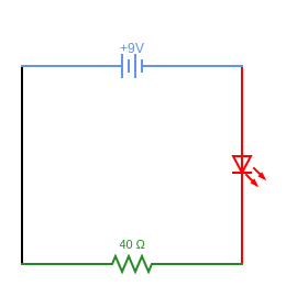
Figure 28: Basic Electrical Circuit
NOTE: We know that electrons are the atomic particles that move to create electricity. We also know that electrons move away from areas containing an abundance of electrons (negatively charge) to areas with too few electrons (positively charged.) However, when electricity was first discovered, it was thought that positive charges moved to negative. This is called conventional flow. In circuit diagrams, the direction of conventional flow is still used. Electrical current flows out of the positive and back into the negative.
Series Circuits
A series circuit has only one path for electrons to flow. In the example above (figure 26), electrons are forced to flow through the resistor, through the L.E.D., and back to the negative terminal of the battery in that order. The resistor and L.E.D. are sequential, or in series.
Open Circuit
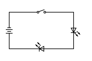
Figure 29 The open switch (top) stops current flow and the two LEDs are off. However, there is still voltage (pressure).
An open circuit exists when a closed circuit has a break in it. This is easily seen by showing a switch.
In an electric circuit, we know that voltage pushes current (amps) through a conductor the same way water pressure pushes gallons of water through a pipe. When the flow of water is stopped by turning a tap off, pressure is still present behind the tap. Similarly, when a switch is opened, the movement of electrons (amps) stops, but voltage is still present (figure 29).
This is the reason why current will only flow in a closed circuit, while voltage can be present in an open circuit.
Short Circuit
Everyone has heard of a “short circuit.” Short circuits develop when a path is connected directly to the voltage source without any (or very little) resistance (load).
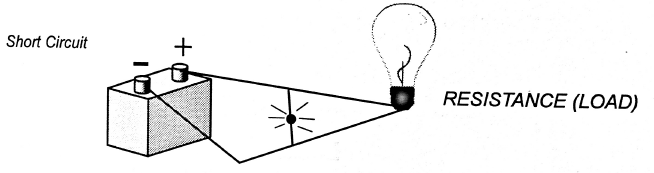
Figure 30 most electrical current bypasses the load and returns to the battery. From SaskPower Training Manual, used with permission.
In this above diagram, there is a conductor that takes a short cut back to the battery, bypassing the load (lightbulb). This creates a short circuit. Electrical current will follow the path of least resistance. Since there is no load on the shortcut path, nearly all current will flow through that conductor. Excessive current will cause heat, and eventually the conductor will burn out potentially causing a fire.
Parallel Circuits
Parallel circuits have more than one path electricity can take. One way to think of a parallel circuit is to have more than one series circuit attached. The following is a circuit diagram of a parallel circuit:
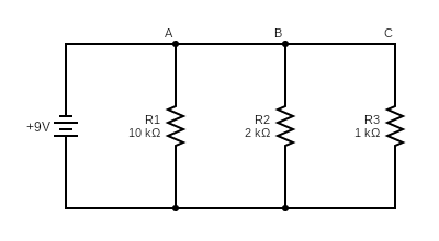
In the above diagram, there are many ways the current can flow:

In fact, current flows through the green, blue and pink paths simultaneously.
A parallel circuit also consists of a voltage source (battery), current carrying conductors, and resistors (loads).
In the next section, we will see how voltage, resistance, and current behave differently in parallel and series circuits.
Practice Exercises
[h5p id=”17″]
Topic 2: Voltage, Resistance and Current in Series Circuits
2.1 Current, Voltage and Resistance
Electricity has three basic and related qualities: Current, Voltage and Resistance. Some parallels can be drawn from a water system to an electrical circuit.
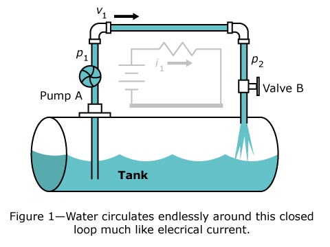
This photo by unknown author is licensed under CC BY-SA
A water pump forces water to flow just as a battery causes electrons to flow. The water is analogous to electrons (electricity.) The valve creates resistance that opposes the water flow. This is analogous to a load (or resistor) in an electric circuit. Note that there is a difference in pressure before and after the valve (if the valve is partially closed.) This difference of pressure is called a voltage drop. The water pressure is analogous to electrical potential, or voltage.
Electric Current
In our water analogy, the amount of water flow could be measured in GPM or gallons per minute. Since rate is defined as an amount per time measurement, we need the number of electrons per second to measure electric current.
We call this measured number of electrons a “coulomb.” Since electrons are so small, it was decided that 1 coulomb would be 6.25 x 10¹⁸ electrons. (That is 6,250,000,000,000,000,000 electrons!)
As with the water system, the flow can be measured in coulombs per second.
Later, coulombs per second (coulomb / sec) came to be measured by a unit called ampere or amp.
Characteristics of Current
- 1 coulomb / sec = 1 ampere, or
- 1 coulomb / 20 sec = 1 / 20 ampere, or
- 20 coulombs / sec = 20 amperes.
- Symbol of a current (I)
- Measured in amperes (A)
- Defined as the flow of electrons in a closed circuit
- Measured with an instrument called the ammeter
Voltage
Voltage is described in many ways meaning the same thing. You will hear it defined as:
- A potential difference between two points
- An electromotive force (EMF)
- The pressure applied to electrons.
Voltage is best described simply as “the potential difference or pressure between two points.” As with current, voltage also has some characteristics of water in a pipe. Instead of an amount of flow (as with current), voltage is compared to the pressure in a water system. Instead of lbs/in2 or PSI (as with water), we measure electrical pressure in volts. Just as pressure is needed to cause water to flow, voltage is needed to cause current to flow. If voltage is not present, current flow is impossible.
Characteristics of Voltage
- Symbol (E), (EMF), or (V)
- Measured in volts
- Defined as the pressure or force that exists between two points of different potential
Resistance
As we have already discovered, for the current to flow (or electrons to leave their orbits), voltage must be applied to the conductor or circuit (in a closed circuit.)
Since current does not flow without the application of this external pressure, we are safe in assuming that the conductor has a natural tendency to resist current flow. All materials’ opposition to current flow is different, depending on how easily their valence electrons are removed.
This characteristic is referred to as resistance and is measured in ohms.
Good conductors have low resistance due to the ease with which their electrons can be removed (copper).
Poor conductors (insulators) have a high resistance to current flow due to their nature to retain their electrons (glass.) Current favours the path of least resistance.
As you can see in our water / electricity comparison, both can have an opposition or resistance to current flow. In the water system, the valve could be partially closed, causing resistance to water flow. In an electrical system, a load (or resistor) creates a similar resistance to electrical current flow.
Characteristics of Resistance
- Measured in Ohms (Ω)
- Symbol of resistance is (R)
- Opposition to current flow
Practice Exercises
[h5p id=”18″]
2.2 Ohm’s Law
Ohm’s Law shows us the mathematical relationship that exists between voltage, amperage, and resistance.
In its simplest form, Ohm’s Law states:

It takes 1 Volt of pressure to push 1 Amp of current through 1 Ohm of resistance.
Using math, we can isolate each of the variables (E, I, R) to calculate voltage, current or resistance.


An easy way to come up with these formulas is to use the “trades person triangle.”
To solve for a variable, cover it and solve as you see Ohm’s Law written. For example:
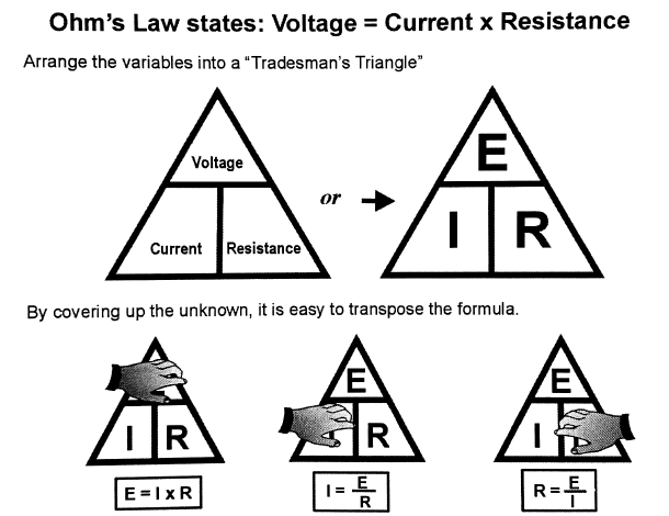
Figure 31 Calculations Using Ohm’s Law. From SaskPower Training Manual used with permission.
Ohm discovered that if resistance was constant and the voltage decreased, there is a proportional decrease of current.
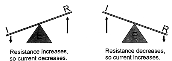
Figure 32 Resistance and current inversely proportional. From SaskPower Training Manual used with permission.
He also found that:
- If voltage remains constant and resistance increased, current decreases.
- If voltage remains the same and resistance decreased, current increases.
Therefore, in a given circuit:
- Current is directly proportional to voltage.
- Current is inversely proportional to resistance.
It should be noted that anytime current flows through a resistor (or any conductor), heat is given off.
Practice Exercises
[h5p id=”19″]
2.3 Determining Total Voltage, Resistance and Current in Series
As we have learned, electric circuits consist of a voltage source (battery), current carrying conductors (wires), and resistances (or loads). Also, a series circuit is defined as a circuit which has only one path for current to flow.
Electric circuits contain a voltage source, current carrying conductors, and resistances. These three components each have a unique characteristic that applies to all series circuits.
Current
Since current has only one path to flow in a series circuit, current is always the same (constant) throughout the circuit.
Therefore:

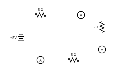
Figure 33 the ammeters (labeled A) all read the same amperage.
In figure 33, the current in the circuit is 1 ampere, no matter where current is measured.

Resistance
The most important thing concerning resistances in a series circuit is that they are added together to find the total resistance.
When resistors (or wires) are connected in series, the total resistance,  , must be equal to the sum of the individual resistances.
Therefore:

In figure 33, the total resistance is the sum of all the resistors (5Ω + 5Ω + 5Ω), or 15Ω. Therefore, the circuit in figure 33 could be simplified as such:
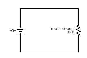
Figure 34 The total resistances add to 15 ohms.
Voltage
Whenever a current passes through a resistor, some of the pressure (or voltage) is used up while forcing it through. Similarly, if you were pushing an object over a barrier, you too would lose energy.
The loss of voltage is referred to as a potential drop or voltage drop.
Kirchoff’s 2nd Law states in a series circuit: “The sum of voltage drops across the resistances of a closed circuit is equal to the total voltage applied to the circuit.”
Therefore,

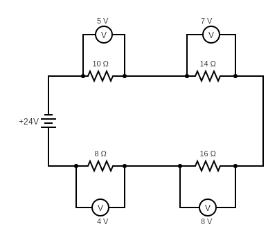
Figure 35 All voltage drops add to 24 V, the total supplied voltage.
In figure 33, voltmeters are represented by ‘V’. We can see four voltmeters measuring the voltage drop across four different resistors. Using the formula:


The volts are used to push the current through all the resistors is equal to the applied voltage.
Ohm’s Law and Series Circuit Properties
Now, we know four important facts about a series circuit:
and
If we know enough information for two of the variables in the formula, we should have no trouble determining the remaining values of complete circuits or portions of circuits.
Example
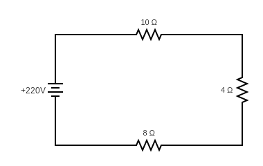
Find the total current in the following circuit
Solution:
The total resistance in this series circuit is:
10 Ohms + 4 Ohms + 8 Ohms or 22 Ohms.
The circuit is energized with 220 Volts of electromotive force.
Ohms law states that:

There are 10 Amps of current in the circuit.
Practice Exercises
[h5p id=”20″]
2.4 Determining Total Voltage, Resistance and Current in Parallel
Ohm’s Law applies to parallel as well as series circuits. However, there are differences in how voltage, resistance, and current behave in parallel.
Parallel Circuits
We have seen in the DC Series Circuits module that:
- Series circuits have only one path for current to flow.
- Series circuits have resistors connected end to end.
By definition, parallel circuits are “circuits that have more than one path for current to flow.”

In the above diagram, there are many ways the current can flow:
A parallel circuit also consists of a voltage source, current carrying conductors (in parallel with each other), and resistors (loads). These each carry a distinct characteristic. We shall study each of them independently.
Current
Since a parallel circuit has more than one path for a current to follow, we can assume the current will be divided up amongst the paths. The amount of current that flows in each path depends on the resistance of each path.
We know from Ohm’s Law that current and resistance are inversely proportional, or:
- As resistance increases, current decreases.
- As resistance decreases, current increases.
Since we know that current will take the path of least resistance, we can see that, if one branch has 30 ohms resistance and one branch has 15 ohms, more current will flow through the resistor offering the least resistance.
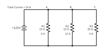
Figure 36 Most current flows where there is least resistance.
We can see in figure 36 that the current in the three branches also equals the total current. This is expressed in Kirchoff’s 1st Law:
Current in a Parallel Circuit
The sum of current leaving a point must be equal to the currents flowing to that point

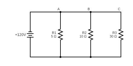
Voltage
If we look at a parallel circuit, we can see that resistances are connected across a voltage source. Since each resistor is connected directly across the power source, each branch will receive the voltage equal to the total applied voltage. This is stated as:
Voltage in a Parallel Circuit
The voltage drop across any branches in a parallel circuit is the same as the total applied voltage

This is why houses are wired in parallel.
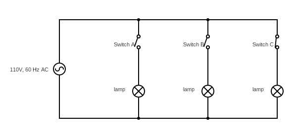
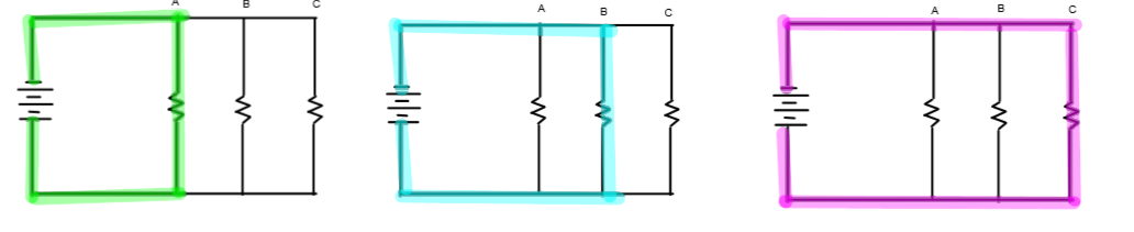
Figure 37 parallel wiring of lamps.
Any number or combination of branches can be “open” or “closed” and not affect the rest of the circuit. In figure 37, even though switch A and B are open, current can still get through switch C lighting the last lamp. Furthermore, there is the same voltage at each load, which is important for the operation of appliances.
Resistance
While being a little harder to understand mathematically, a commonsense approach shows us resistance in a parallel circuit is actually quite simple.
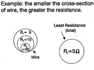
We know one factor that affects the resistance of a conductor is the wire size or cross-sectional area. A large wire will allow more amps to flow than a small wire because it has less resistance. Adding a conductor in parallel also lowers resistance.
A good example is bundled conductor on high voltage lines. Resistance is lowered, so current carrying capabilities are increased.
If we had a circuit where electrons could only travel through one 2/0 wire, resistance is constant. If we add another 2/0 wire in parallel, we now have two paths for current to flow. Since two 2/0 wires are larger than one 2/0 wire, we can see our resistance to flow is reduced. (In the same manner that using a larger wire would reduce resistance.)
Since each time a conductor is placed in parallel resistance decreases, we can see that the total resistance of a parallel circuit is always less than the smallest resistor.
Calculating Resistance in a Parallel Circuit
Resistors of Equal Value
If the circuit is made of numerous resistors that possess the same value, you simply divide the common resistance value by the number or resistors in the circuit.
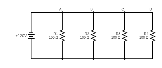
In this case, the total resistance of the circuit is 100 Ohms divided by 4 paths is 25 Ohms overall resistance. Even though the resistance on each path is 100 Ohms, there are 4 paths to follow, so the overall resistance is less.
Resistors of Unequal Values
The sum of resistances in this case is a little more difficult. The best way would be to use an ohmmeter.
Since this isn’t always possible, there is a formula to use to calculate the total resistance of parallel circuits.
Resistance in a Parallel Circuit

Consider this circuit diagram:
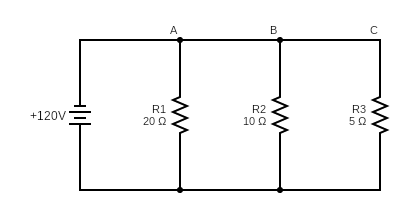
To solve for the above equation, we can see that


Ohm’s Law and Parallel Circuits
We now know three important facts about a parallel circuit:
We can use these properties and Ohm’s Law to solve some parallel circuits
Example
Four resistors are connected parallel to a 120 volt source. The resistors are 8 ohms, 12 ohms, 1 ohm, and 7 ohms as shown below.
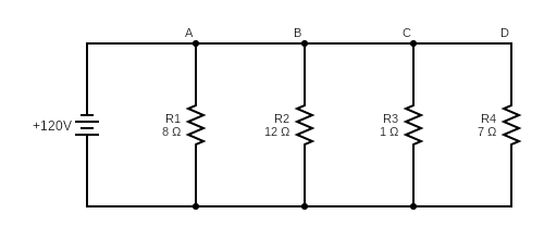
What is RT, IT, I1, I2, I3, and I4?
To solve for RT (total resistance):


To solve IT:


To solve E1, E2, E3, E4:
All the voltage drops are equal in a parallel circuit. All voltages are 120V.
To solve I1, I2, I3, and I4:
Use Ohm’s Law at each intersection:


You can check your answer by adding all the current values to see if they match the previously calculated value of 162 Amps.
Practice Exercises
[h5p id=”21″]
Topic 3: Electrical Measuring Instruments
The digital multimeter is almost always used to test electrical properties. The multimeter is a combination of several instruments used in the past:
- Galvanometers, to measure electromotive force (voltage),
- Ammeters, to measure current in amps,
- Voltmeters, to measure volts, and
- Ohmmeters, to measure resistance in Ohms.
We will talk about these instruments in the following sections.
This Photo by Unknown Author is licensed under CC BY-SA-NC
Ammeter
An ammeter measures current in amperes (A) and must be hooked in series.
- Ammeters have very low resistance so most of the current travels through the ammeter
- A voltage drop is measured and the current is calculated by the ammeter (V = I X R)
- Only 10 – 30 Amperes (depending on ammeter) can be measured for a short period of time (5 seconds)
Ammeters are typically ranged as follows:
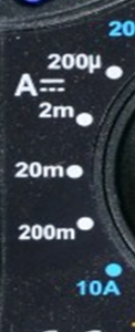
- Amperes
- Milli amperes (mA) (one thousandth 1/1,000 of an ampere)
- Micro amperes (μA) (one millionth 1/1,000,000 of an ampere)
|
Notes for Safety:
|
Voltmeter
A voltmeter measures voltage (V) or the potential difference between two points and must be hooked up in parallel (directly across the source of power).
Since it is hooked up in parallel, we can draw the conclusion that, unlike an ammeter, its resistance must be very high. Since we know current flows easier through a low resistance than a high resistance, it is safe to say almost all the current will flow through the other circuits.
Also, a voltmeter cannot be hooked in series because its high resistance would make it virtually impossible for any electrons to flow.
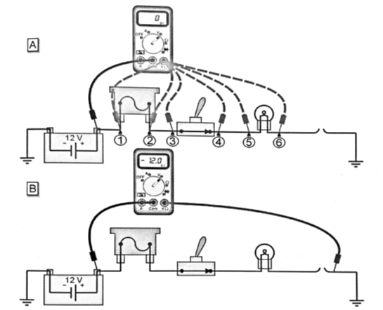
Figure 38 Finding the fault in an open circuit. From SaskPower Training Manual, used with permission.
Voltage is not a thing that is measured at one point, it is measured across a part of the circuit. To find an open (broken) circuit as in figure, start testing at the source, and measure at points along the circuit. At each measurement before the open, the voltmeter will read 0 (diagram A). Once you move the voltmeter past the open, it will read the source voltage, 12 volts in this case (diagram B).
Ohmmeter
An ohmmeter measures resistance in ohms and has its own power source. (You do not use an ohm meter on an energized circuit.) An ohmmeter can be tested quickly before use:
- Leads held together. This will simulate a short circuit or a circuit with very little resistance. The resistance should be very close to zero.
- Leads held apart. Since air is an excellent insulator, no current will flow. This open circuit will read as infinite or overload as such:
- OL for overload
- OR for over range
- Flashing 1000
Ohmmeters are typically ranged as follows:
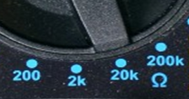
- 200 Ohms Ω ( can read up to 200 Ohms)
- 2 k Ω (can read up to 2 kilo ohms or 2,000 ohms)
- 20 k Ω (can read up to 20 kilo ohms or 20,000 ohms)
- 200 kΩ (can read up to 200 kilo ohms or 200,000 ohms)
- Any larger resistance will read open circuit
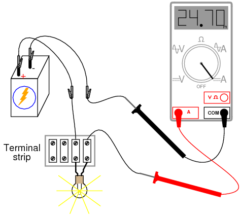
Proper use of an ohmmeter:
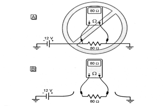
Figure 39 Proper use of an Ohmmeter. Image from SaskPower Training Manual, used with permission.
Ohmmeters must be connected in series with the component being tested. The component must be isolated from the rest of the circuit. The component must not be energized.
Digital Multimeter
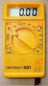
Figure 40 Manually ranged digital multimeter, from Wikimedia commons.
A digital multimeter can measure voltage, current and resistance (rather than having one tool for each). Digital multimeters have a digital read out. In manual range multimeters, you need to select the correct range on the dial. In more modern automatic ranging multimeters, manual range selection is not necessary.
Analog Multimeter
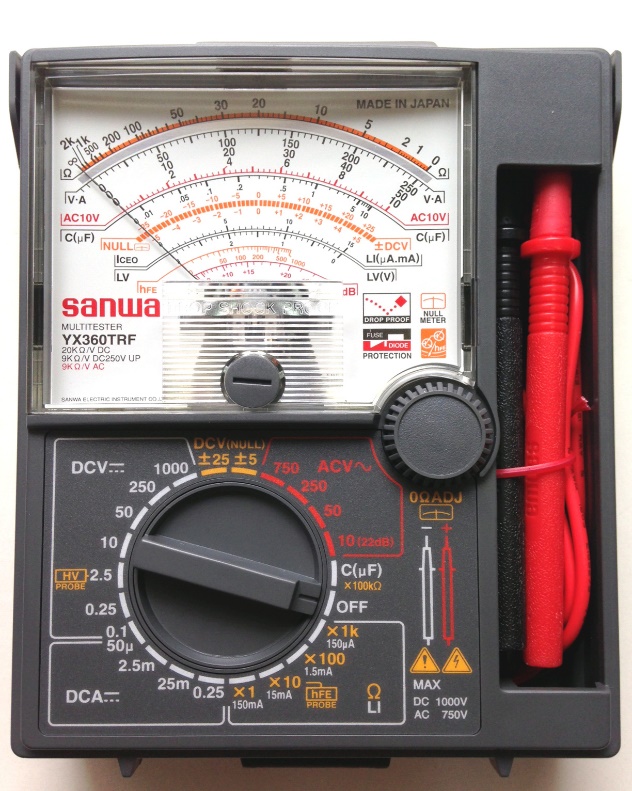
Figure 41 Analog multimeter, from Wikimedia commons.
Analog multimeters have a needle on a dial read out. These types of multimeters are outdated and generally are not used.
In a manually ranged multimeter, you must select the setting for the range of voltage you expect the circuit to contain. Often, start high, and if nothing is read, move down. For example, the voltage being measured Is 155 mV.
- Starting at the 1000 V setting (voltages up to 1000 V), 0 will be read
- Moving down to the 200 V setting, 0.1 may be read
- Moving down to the 2 V setting, 0.155 will be read
- Moving down to the 200 mV setting, 155 will be read.
In auto ranging multimeters the range is automatically set to the most accurate scale.
Current Clamp
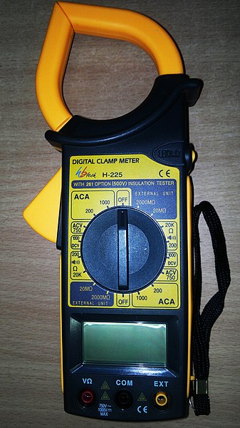
Figure 42 Inductive ammeter (current clamp) form Wikimedia commons.
As we have learned, moving current will induce a magnetic field. If the strength of the magnetic field is measured, you can calculate how much current is flowing. The advantage to this is you do not need to physically clamp into the conductor to measure current, you can measure the magnetic field close to the conductor.
An inductive ammeter (referred to commonly by the brand name Fluke), measures the current through a conductor using the properties of induction.
Wattmeter
A wattmeter measures watts (W), which is the product of voltage and current (power = voltage X current)
Watts can be calculated with voltmeter and ammeter readings. This is done in some instances, but it is easier to use a wattmeter.
A normal house meter is a variation of the wattmeter.
Practice Exercises
[h5p id=”22″]
Topic 4: Alternating Current (AC) and Direct Current (DC)
“Starting in the late 1880s, Thomas Edison and Nikola Tesla were embroiled in a battle now known as the War of the Currents.
Edison developed direct current – current that runs continually in a single direction, like in a battery or a fuel cell. During the early years of electricity, direct current (shorthanded as DC) was the standard in the U.S.
But there was one problem. Direct current is not easily converted to higher or lower voltages.
Tesla believed that alternating current (or AC) was the solution to this problem. Alternating current reverses direction, a certain number of times per second — 60 in the U.S. — and can be converted to different voltages relatively easily using a transformer.
Edison, not wanting to lose the royalties he was earning from his direct current patents, began a campaign to discredit alternating current. He spread misinformation saying that alternating current was more dangerous, even going so far as to publicly electrocute stray animals using alternating current to prove his point.
The Chicago World’s Fair — also known as the World’s Columbian Exposition — took place in 1893, at the height of the Current War.
General Electric bid to electrify the fair using Edison’s direct current for $554,000, but lost to George Westinghouse, who said he could power the fair for only $399,000 using Tesla’s alternating current.
That same year, the Niagara Falls Power Company decided to award Westinghouse — who had licensed Tesla’s polyphase AC induction motor patent — the contract to generate power from Niagara Falls. Although some doubted that the falls could power all of Buffalo, New York, Tesla was convinced it could power not only Buffalo, but also the entire Eastern United States.
On Nov. 16, 1896, Buffalo was lit up by the alternating current from Niagara Falls. By this time General Electric had decided to jump on the alternating current train, too.
It would appear that alternating current had all but obliterated direct current, but in recent years direct current has seen a bit of a renaissance.
Today our electricity is still predominantly powered by alternating current, but computers, LEDs, solar cells and electric vehicles all run on DC power. And methods are now available for converting direct current to higher and lower voltages. Since direct current is more stable, companies are finding ways of using high voltage direct current (HVDC) to transport electricity long distances with less electricity loss.
So it appears the War of the Currents may not be over yet. But instead of continuing in a heated AC vs. DC battle, it looks like the two currents will end up working parallel to each other in a sort of hybrid armistice.
And none of that would be possible without the genius of both Tesla and Edison. “
Extracted from https://www.energy.gov/articles/war-currents-ac-vs-dc-power on October 1, 2021
Practice Exercises:
[h5p id=”23″]
