10 Topic: Guys and Anchors (10m)
Instructions:
- Cover the following content as a group (either reading out loud or independently) then give an opportunity to answer any questions.
- Have students do the review questions independently, then take up answers.
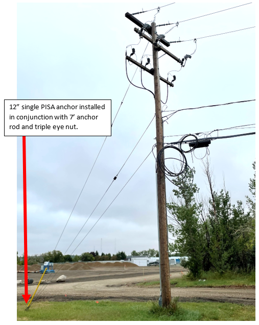
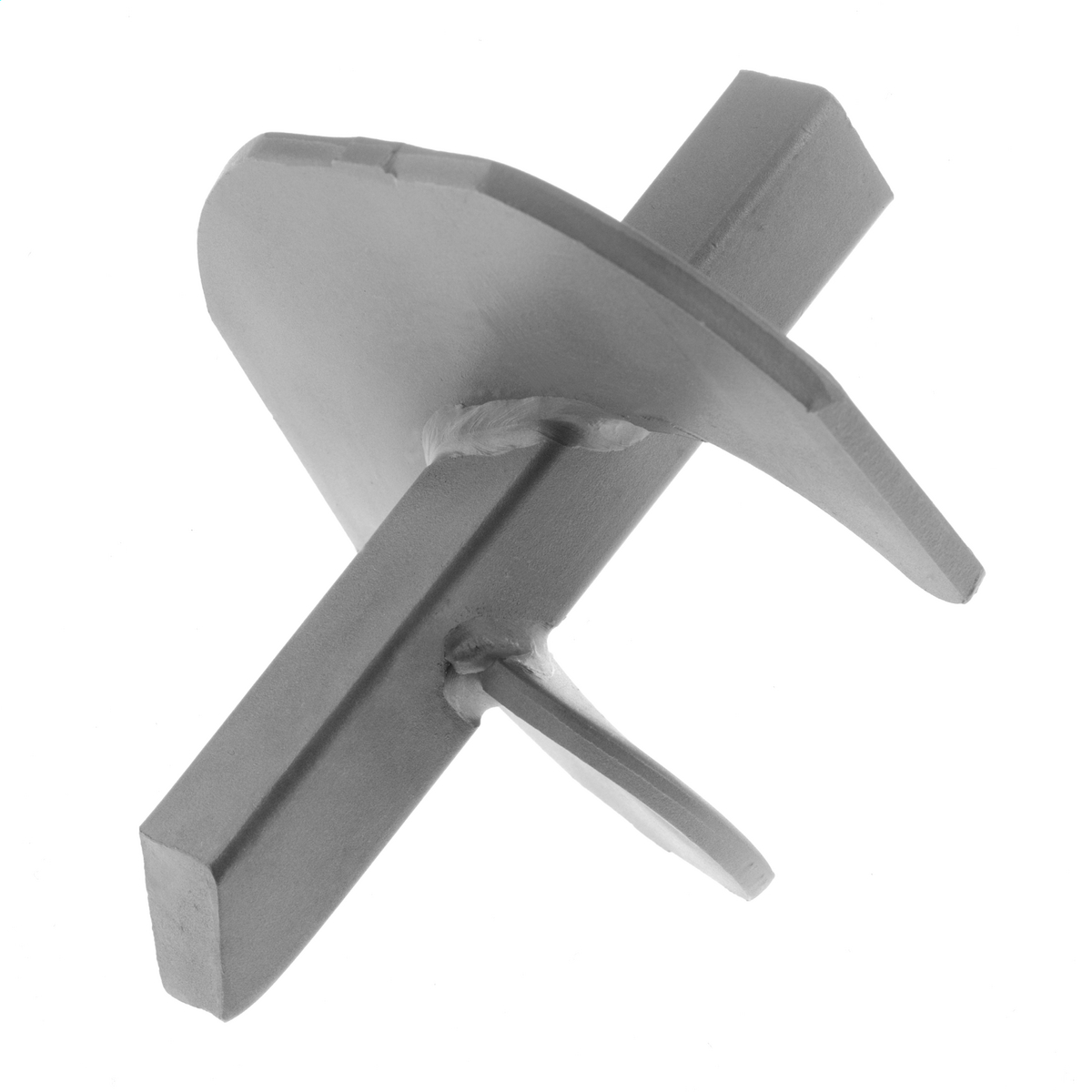
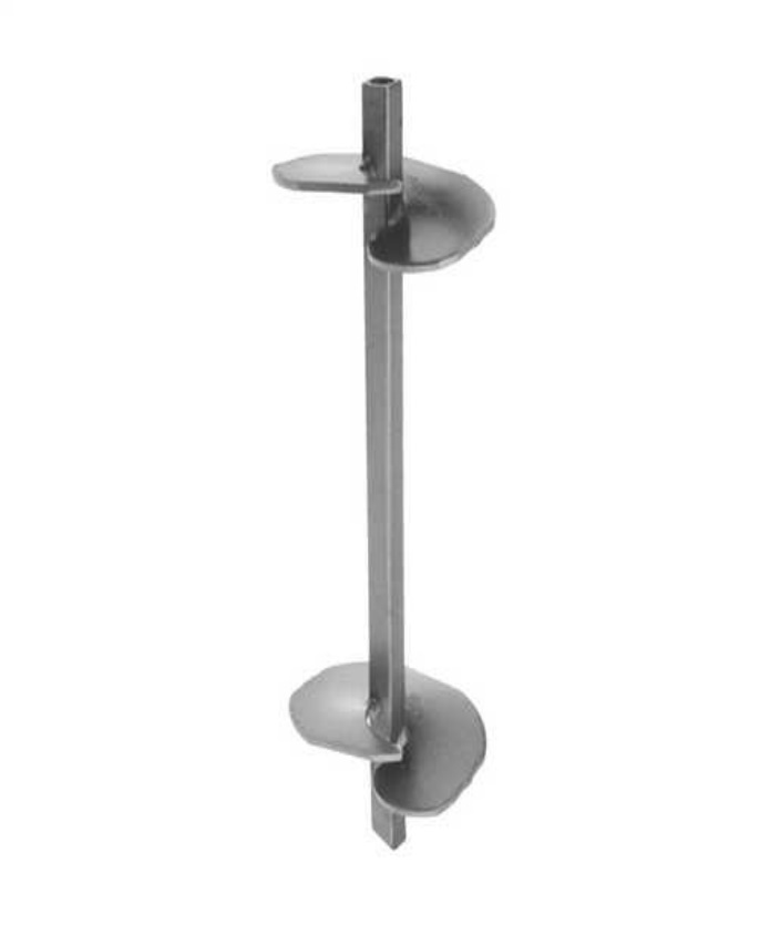
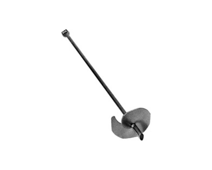
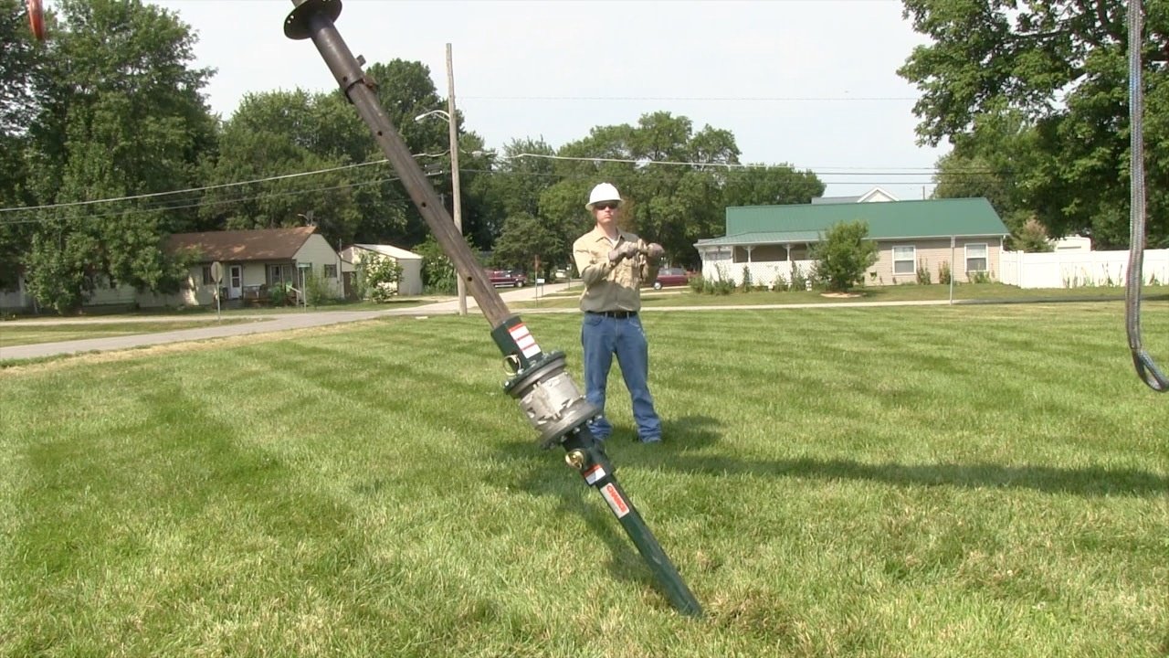
Power installed anchors (PISA) are used to carry the strain of overhead conductors attached to poles in conjunction with guy wires and fiber strain insulators. PISA anchors are screwed into the earth to anchor the structure’s load. Anchors come in a variety of sizes and either single or multiple flights are used dependent upon the soil conditions and the amount of strain to be carried.
 |
 |
 |
|
Applications in Line Construction (30m)
You have learned how to calculate the angles and lengths involved with right angle triangles. You can use this information and the parallelogram method to solve tensions for guys, conductors, and the stress on poles which we call compression.
Example 1
In the drawing below, a line 15m in the air has 800 lbs. of tension with an anchor 15m from the pole.
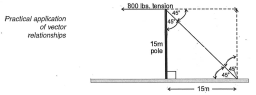
Find:
- The length of the guy
- The tension on the guy
- The compression on the pole
Solution
a) Length of Guy
c2=a2+b2
c2=152+152
c = 21.2m
b) Tension on guy
Since the two sides of the right angle triangle are of equal length, the angle is 45 degrees. Find the hypotenuse:
cosθ=adj/hyp
cos 45°=800/hyp
0.707=800/hyp
(0.707) hyp=800
hyp= 8000.707 = 1131.5lbs
c) Compression on the pole
800 lbs., because a 45 degree right angle triangle is equal on both sides.
Example 2:
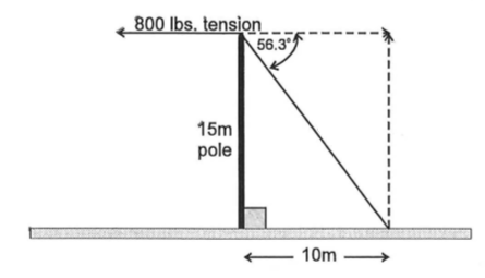
From the above example, what happens when the anchor is moved in 5m as shown in the diagram below?
Find:
- Length of guy
- Tension on guy
- Compression on pole
Solution
a) Length of Guy
c2=a2+b2
c2=102+152
c=18.03m
b) Tension on Guy
cosθ=adjhyp
cosθ=1018.03=56.3°
Therefore,
cos56.3°=800hyp
0.555hyp=800
hyp=8000.555=1441.4lbs
c) Compression on Pole
tanθ=oppadj
tan56.3°=opp800
1.499=opp800
opp=1199.5lbs
Example 3:
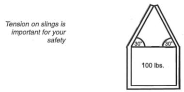
Weight with Slings
To calculate the tension on a sling, you must realize it would take two slings to raise the load. The load is effectively split 50% on one sling, and 50% on the other.
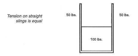
If you make a vector out of the sling angles, you can solve the tension easier.
You know that the slings can be represented as two straight lines as shown below.
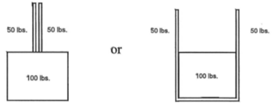
These can be solved using vectors in much the same manner as the pole and guy wire examples.
|
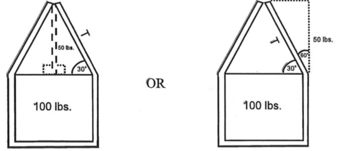
sinθ=opp/hyp TensionSling=sin30°=50T T=100lbs. per sling |
cosθ=50/T Tension Sling=cos 60°=50/T T=100lbs.persling |
NOTE: If the sling angle was reduced from 30 degrees to 10 degrees, there would be 288 lbs. of tension on the slings. (Even though the load is only 100 lbs.)
Review Questions: Guys and Anchors (30m)
- Use the diagram below to find the following:
- Length of guy-wire
- Angle of the guy-wire to the ground
- Tension on guy-wire
- Compression on the pole
- What would be the solution to Question 1 if the guy was moved in 4 metres?
- Length of guy-wire
- Angle of the guy-wire to the ground
- Tension on guy-wire
- Compression on the pole
- By looking at the values in Questions #1 and #2, why do we put 45 degree angles on our guys?
- The job at hand requires you to rig a 50kVA transformer using two 1-metre slings. The transformer weighs 350 kg. The slings must be rigged so the tension does not exceed 200 kg per sling.
- What must the angle be where each sling meets the transformer?
- What would the tension on each sling be if the above angle was decreased to 15 degrees?
Answer Key
1 a. 16.97m, b. 45 degrees, c. 4243N, d. 3000N compression on pole.
2 a. 14.4m, b. 56.3 degrees, c. 5406N, d. 4497N
3. causes less strain on the poles and guys. You don’t want to stress your guys out.
4. a. 61 degrees, b. 676 kg
