Complex Shapes
In this tutorial, we will model 2130005A which will require the use of the midplane and offset reference geometry tools. You will also use a new sketch tool called Convert Entities in this tutorial. To help you follow along with this written tutorial, there are also video tutorials throughout this section.
Base Revolve & Offset Planes
To start this part, open SolidWorks and start a new part with IPS units and ANSI Standard set. Start a new sketch on the Right Plane in preparation for a revolved feature.
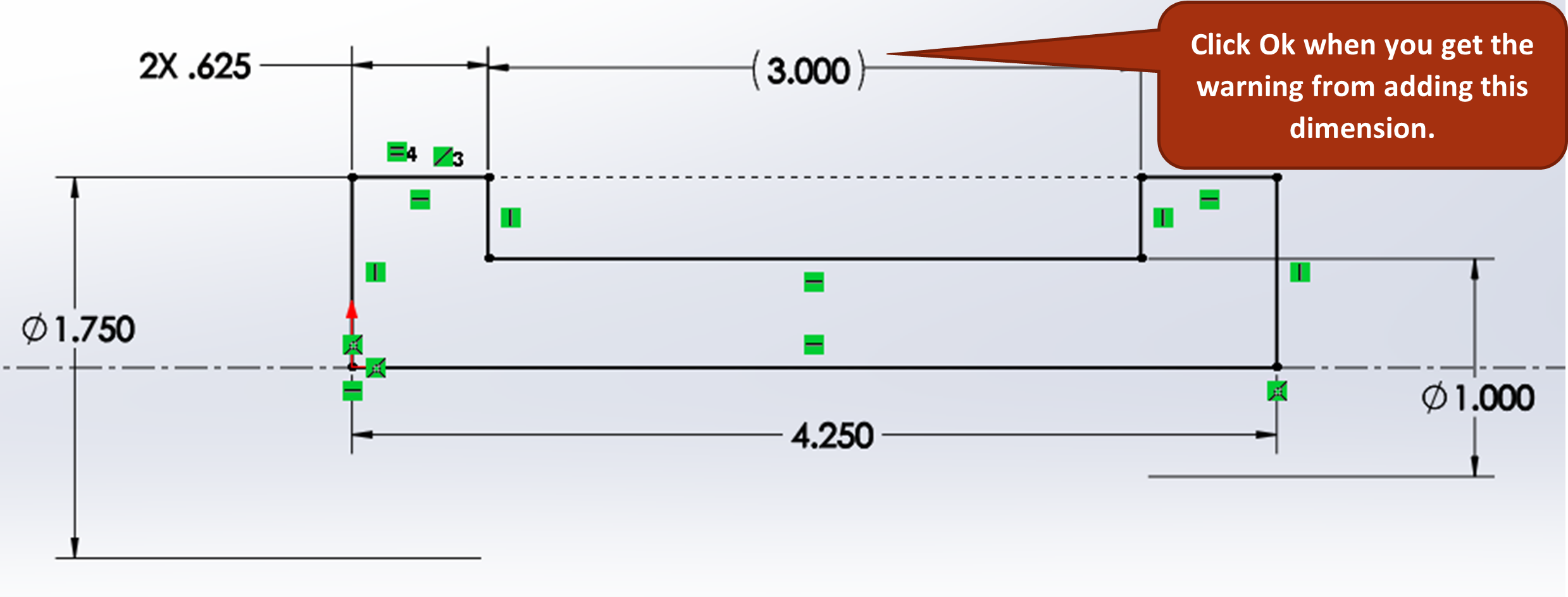
Sketch the top half of the outline of the part shown in the right view of the drawing without the cam lobes (see figure 6.9). Remember that you need a centerline in your sketch. The one for this part goes best horizontally from the origin. You can also try using the infinite line option.
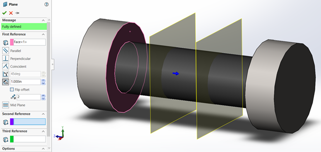
Exercise 6.2 Base Revolve and Offset Planes
Lobe Sketches and Extrudes
Start a new sketch on the leftmost plane of the two you’ve just created and draw the sketch shown in figure 6.11. You should start with a 1.125” diameter circle at the origin, a smaller 7/32” radius circle directly above it (use a vertical centerline to ensure the two circles are vertical). Then draw an arc on one side that is tangent to the 2 circles and has a radius of 2-inches.
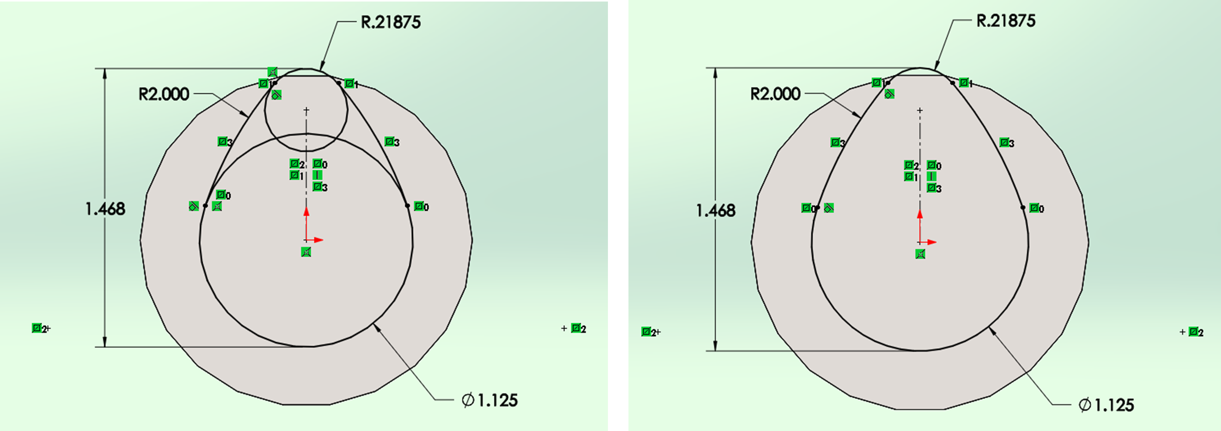
You can then mirror the arc to the other side using the vertical centerline. To get the 1.468 dimension to go to the maximum arc distances, you will have to select the dimension, switch to the leaders’ tab of the property manager, scroll down to the bottom and switch both the first and second arc conditions to max.
When everything is fully defined, trim away the excess. Trim in a chain sequence as to not eliminate any relations that you added. Extrude the cam lobe using the midplane option for the boss extrude direction to .500”. Confirm the boss extrude.
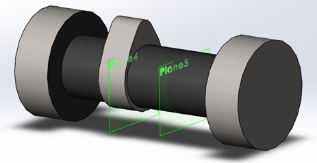
Start a new sketch on the right reference plane of the two you added, click the right surface of the cam lobe you’ve just created, and click the “Convert Entities” button from the Sketch tab of the CommandManager. The outline of the cam lobe should now appear on your new sketch plane. Convert all the entities you’ve just retrieved with Convert Entities to Construction Geometry (figure 6.13).
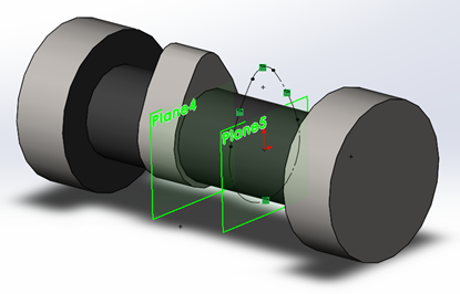
Draw a horizontal centerline from the origin of the sketch to the right, activate the mirror entities command and mirror the lobe sketch entities across the horizontal centerline. After performing the mirror, convert the mirrored entities to solid lines, then extrude to 0.500 inches using the extrude midplane option (Figure 6.14).
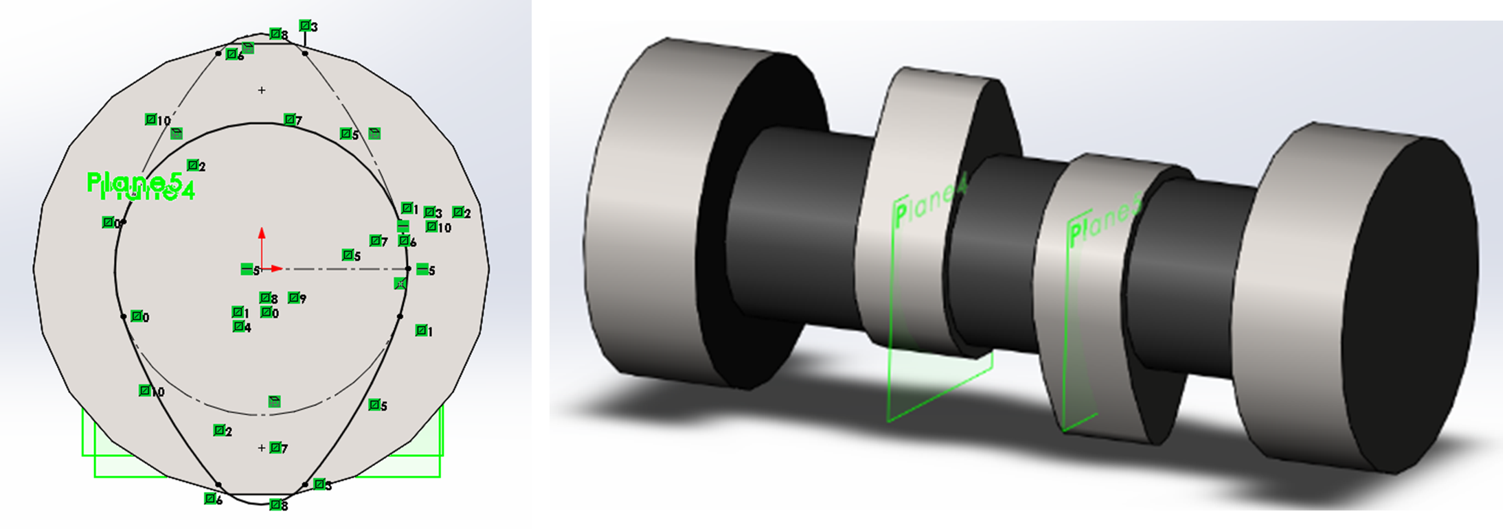
Exercise 6.3 Lobe Sketches and Extrudes
Reference Midplane, Holes, Fillets, Chamfers
Create a reference midplane using the right most and left most faces of the camshafts. This will put a new plane directly in the middle of the part (figure 6.15).
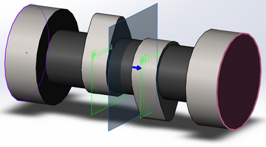
Then activate the hole wizard to place a 5/16” countersunk hole on the right end face of the camshaft directly in the middle on the origin having a depth of .500-inches. Use the mirror feature and the new midplane created to mirror the countersunk hole wizard hole to the other side.
Hide all reference frames by left clicking them and choosing the eyeball with a slash through it from the context toolbar that appears as you select each reference plane.
Add the fillets and chamfers using the 3D fillet and chamfer tools as specified in the drawing, the material, and save.
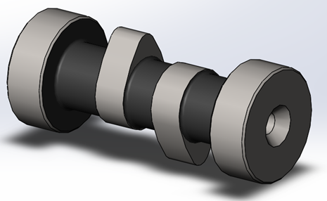
Exercise 6.4 Midplane, Holes, Fillets, and Chamfers
Convert Entities is a sketch tool that allows you to convert existing model edges visible through a sketch plane into sketch entities such as lines, arcs, and points. See SolidWorks Help: Convert Entities.
