Complex Shapes
In this tutorial we will model 2130006_BikeFrame which will require the creation of reference planes based on a reference sketch. The sketches will be simple – two circle a couple lines at most – but because of the capabilities of reference planes, we will create the complex geometry of a portion of a bike frame.
To begin, start a new part in SolidWorks with the units set to IPS and the drafting standard set to ANSI.
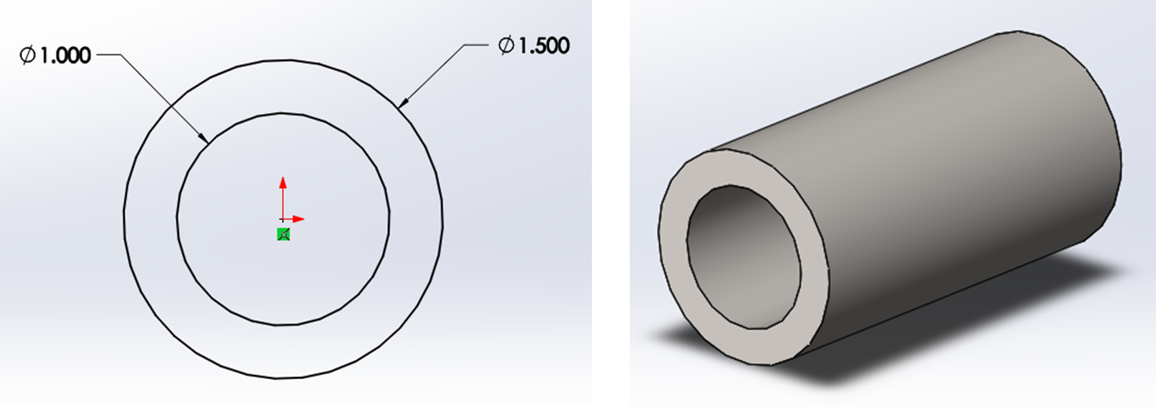
Start a new sketch on the Right plane that is composed of two circles 1.5 and 1-inch in diameter centered on the origin. Extrude the sketch from the midplane to 3-inches.
Start another new sketch on the right plane and draw a centerline vertically. Then draw two angled solid lines on both sides of the centerline from the origin, the left at 60 degrees and the right at 20 degrees. Specify the angles with the smart dimension tool by selecting the lines.
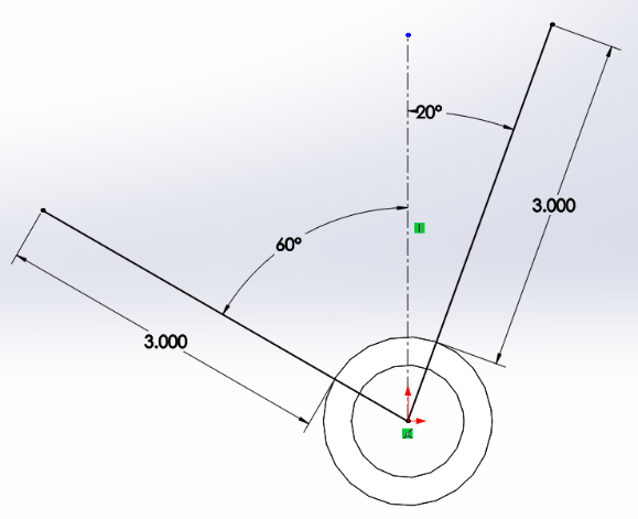
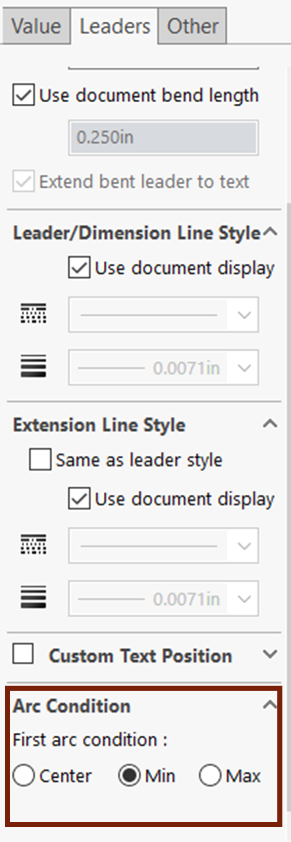
Add 3-inch smart dimensions between the ends of the solid lines and the 1.5-inch circle making sure the dimensions are from the edge of the 1.5-inch circle (you can change this from the leaders’ tab of the property manager of the dimension).
Exit the sketch, activate the reference geometry plane tool and choose the end point of the right solid line from the previous sketch as well as the actual solid line. This makes the endpoint a reference for what the plane needs to go through and the solid line a reference for what the plane needs to be perpendicular to. Confirm the reference plane and then repeat for the left solid line.
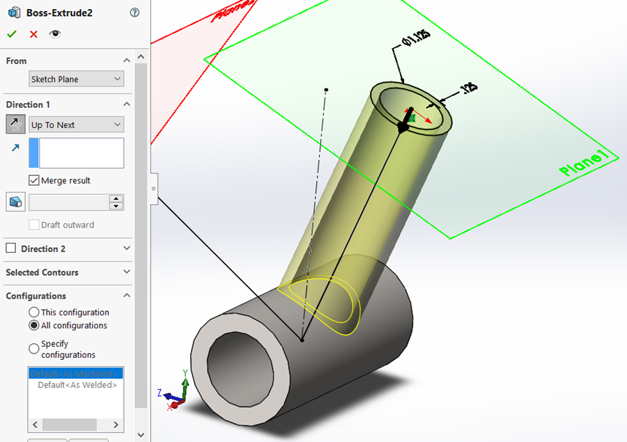
Draw a sketch on the first reference plane you created of two circles centered on the origin with the outer diameter being 1.125-inches and the wall thickness being .125” (choose both circles with the smart dimension tool activated).
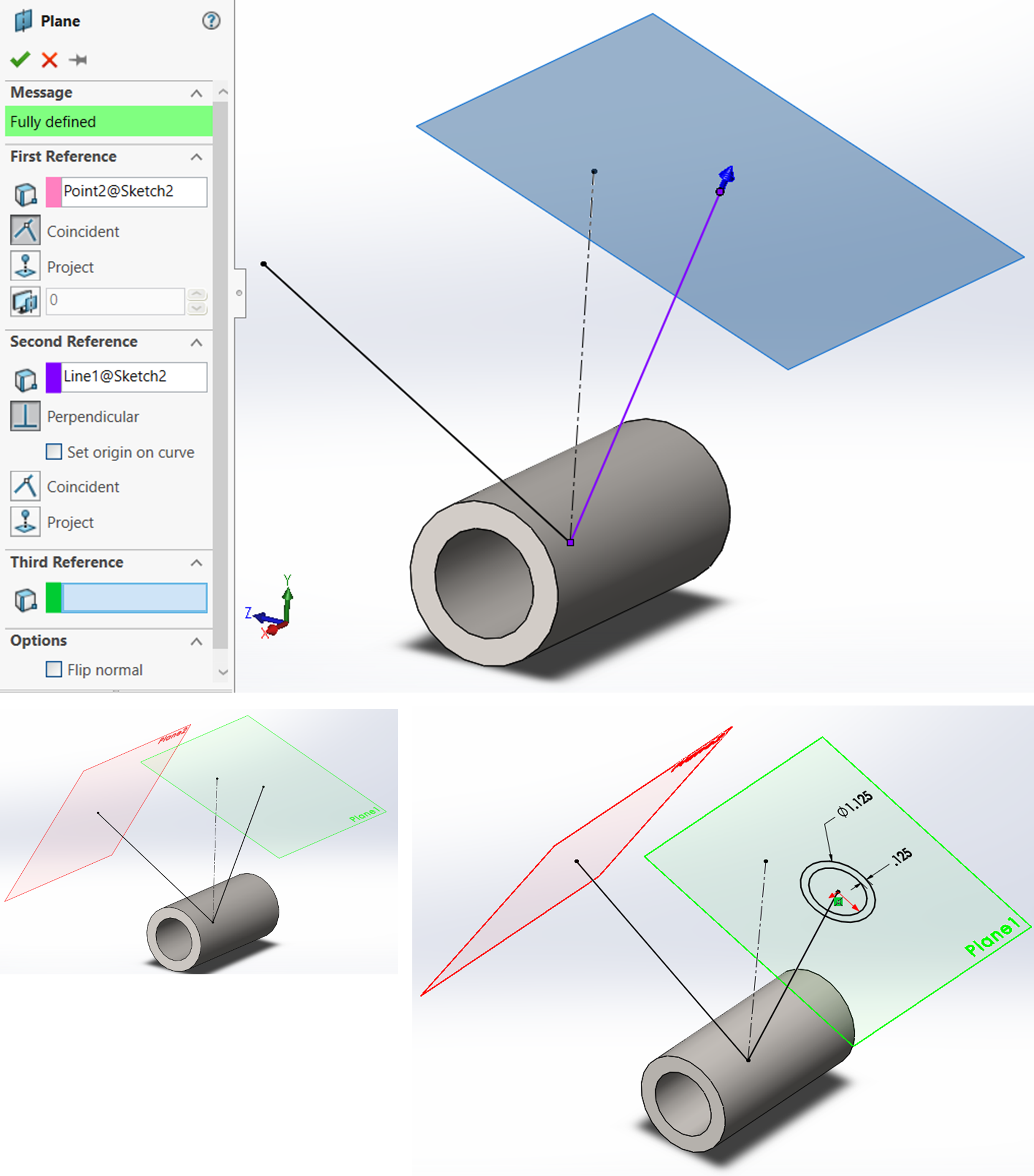
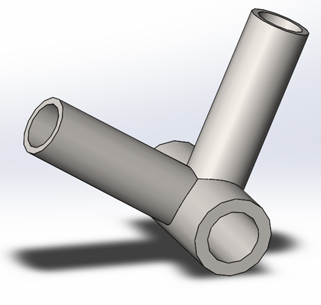
Extrude the sketch with the “Up to Next” option selected and confirm. Repeat this process for the other sketch plane. Hide the reference planes and sketch, specify the material and save.
Exercise 6.5: Partial Bike Frame Tutorial Using Reference Planes and Reference Sketches
