Advanced Sketching Tutorials
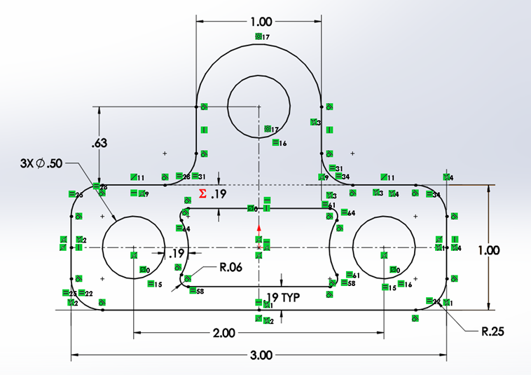
The part we will be creating in this tutorial is like the bracket shown in the previous chapter. You can find a PDF drawing for the part named 2130003 Drawing linked.
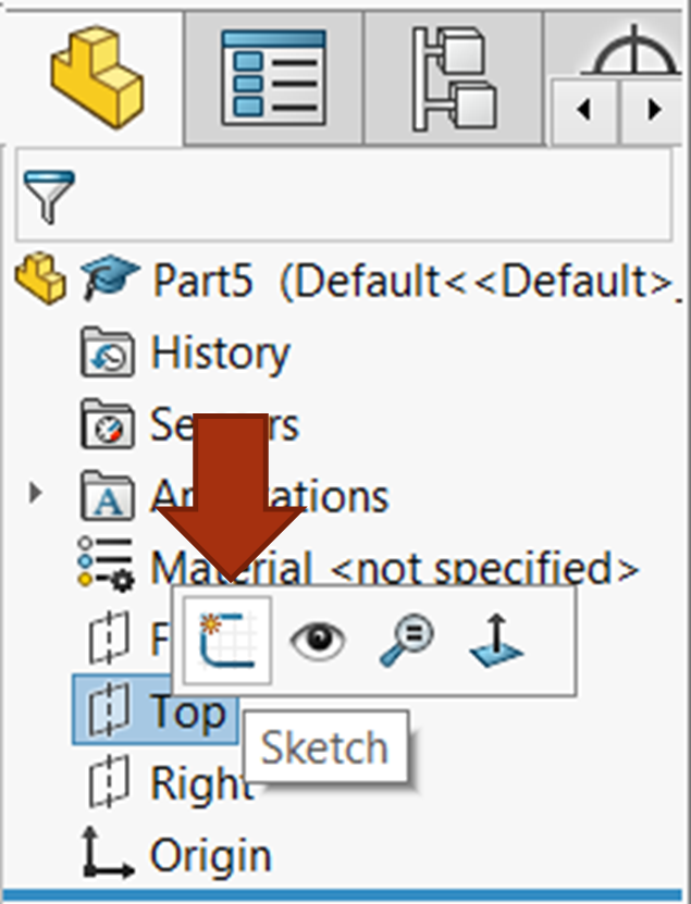
First start SolidWorks and open a new part. If you get the default settings dialog box, choose IPS and ANSI for the units and drafting standard. Start a new sketch on the top plane by clicking the top plane in the FeatureManager Design Tree and selecting the “Sketch” icon.
The Center Rectangle
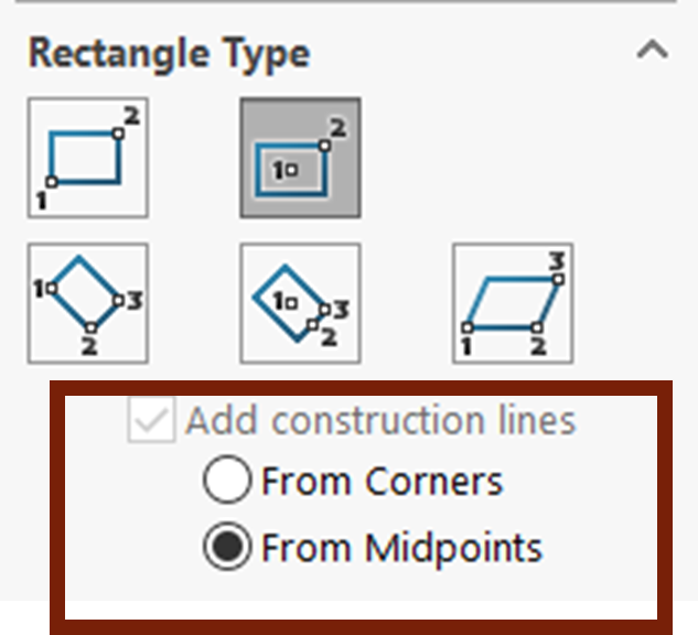
Activate the center rectangle command from the rectangle drop down on the Sketch tab. Before placing the first point, be sure to check the radial button in the property manager for “From Midpoints” (Figure 3.3).
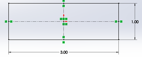
Then place the center point of the rectangle at the red origin, bring your cursor outward to expand the rectangle, click to secure the rectangle into place, and add Smart Dimensions on the length and width of the rectangle 3 inches and 1 inch.
Draw two circles being sure to place their center points on the horizontal centerline, on the left and right sides (Figure 3.5). This will add automatic coincident relations. To do this, activate the circle command from the CommandManager, left click the horizontal center line on the left side of the vertical centerline and then bring your cursor outward to expand the circle, click to secure the circle into place, and do the same thing for the right side of the vertical center line. Add a Smart dimension to only the left circle at a diameter of .50”.
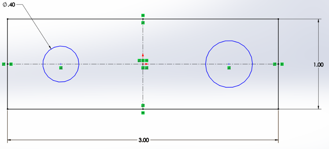
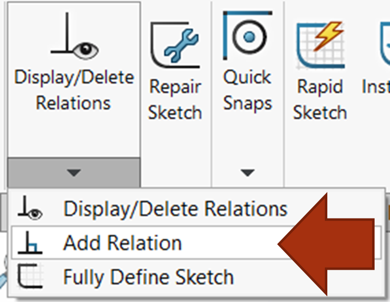
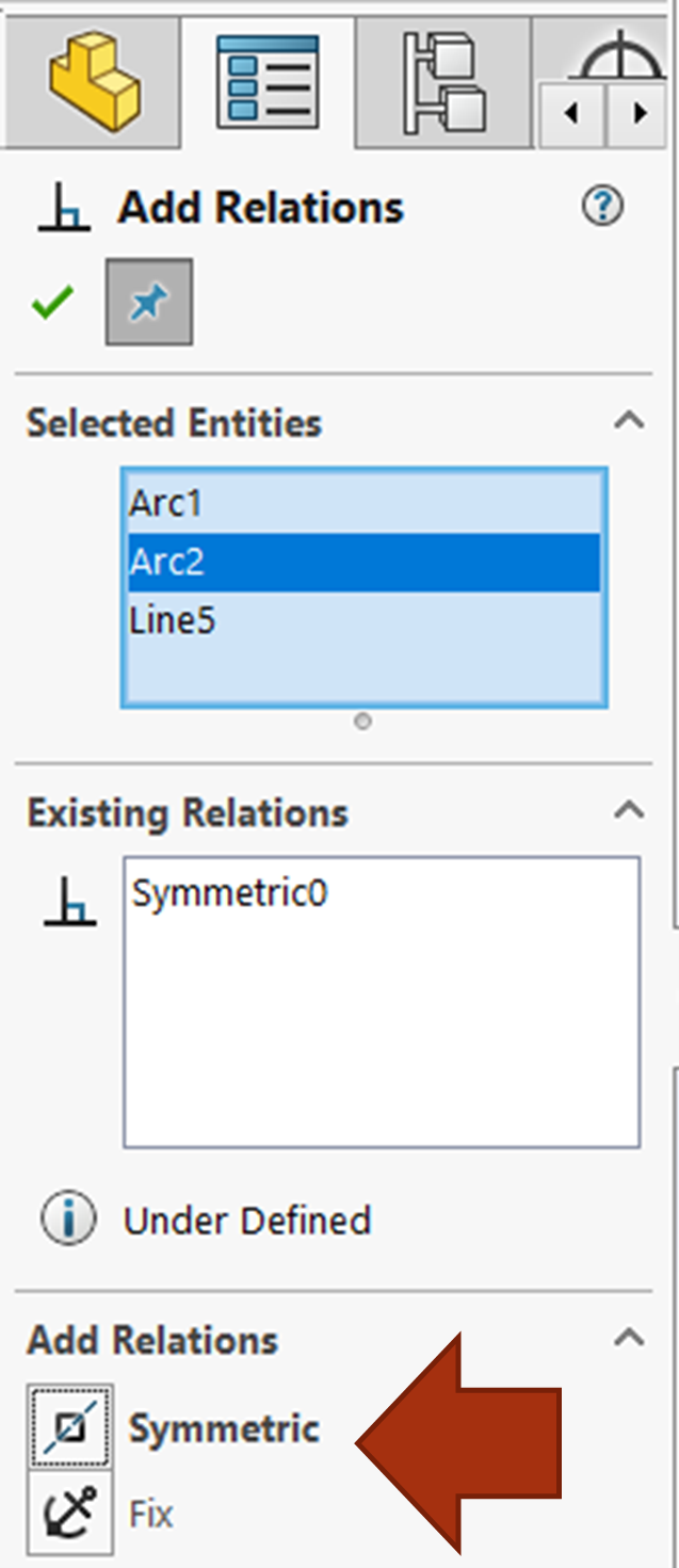
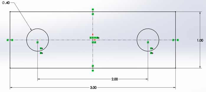
Activate the “Add Relation” command from the “Display/Delete Relations” drop down (figure 3.6) and then select the two circles along with the vertical centerline. When all three are selected, “Symmetric” should be an option for available relations: select the “Symmetric” relation (Figure 3.7). Also add a Smart dimension between the two circle centers that is two inches (Figure 3.8).
Exercise 3.1: Video Tutorial of Center Rectangle Portion of the Bracket
Here is a video tutorial version of the instructions written above.
Offsetting and Trimming a Cutout
After you have added the dimension, activate the Offset Entities tool (this will automatically get you out of the Smart Dimension tool). Offset the two circles outward .1875” as shown in figure 3.9. Click the “Reverse” box in the property manager if needed. Confirm the offset for the two circles.
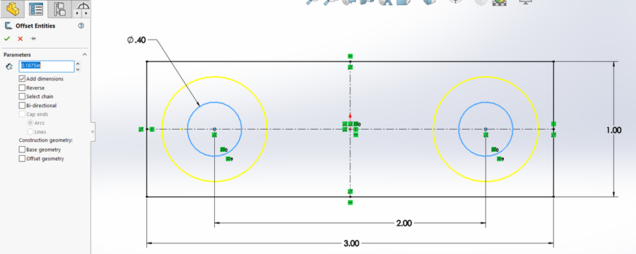
Now offset the top and bottom line of the rectangle inward by the same amount (make sure “Select Chain” is not selected in the property manager and click one edge of the rectangle). You will have to activate the Offset Entities tool again. Confirm the command with the green check mark.
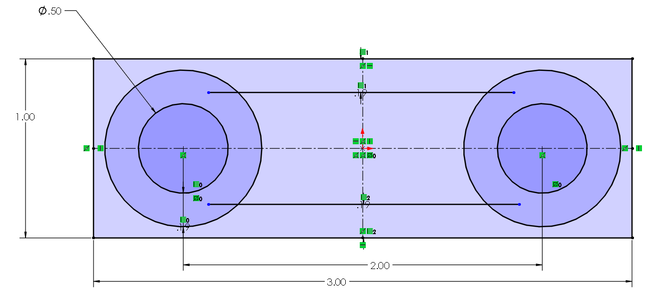
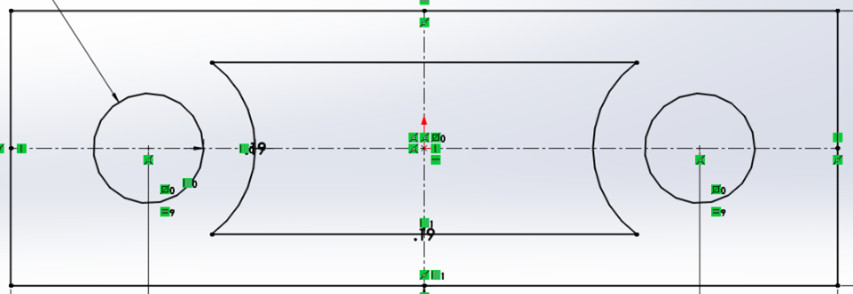
With all these lines everywhere, we must do some trimming to get closer to the cutout shown in the drawing. Activate the Trim Entities tool from the CommandManager. Left click drag through all the unwanted lines; your result should be that shown in figure 3.11. Confirm the trim tool with the green check mark when you are finished.
Exercise 3.2: Video Tutorial of Trimming and Offsetting the Cutout
Here is a video tutorial version of the instructions written above.
The Upper Clevis Portion of the Bracket
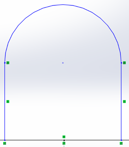
Activate the line command, draw a line starting from the left side of the top line of the rectangle upward, following the blue guide-lines for making an automatic vertical relation (Figure 3.12).
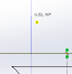
Left click to confirm the line upward, then move your cursor out from the point and then back to the same point. When you move your cursor out again, you will notice that your rubber band line has become a rubber band arc. Bring the arc to the right past the middle of the part to create a perfect semi-circle. The blue guides will help. Click to confirm the semi-circle, then move your cursor directly downward to the upper horizontal of the rectangle. You will notice your line reverted back to a rubber band line. Click on the upper horizontal to confirm the endpoint of your line and double click fast to exit the line command. Confirm that your sketch matches figure 3.13.
Trim the portion of the upper horizontal line on the rectangle that is within your new arch sketch. Then left click drag the upper point of the vertical centerline in the middle of the part closer to the center of the arc. Activate the “Add Relation” command, select the center point of the arc so that both the top centerline point and center of the arc appear in the selection box of the “Add Relation” property manager, and select the “Merge Points” option (Figure 3.14).
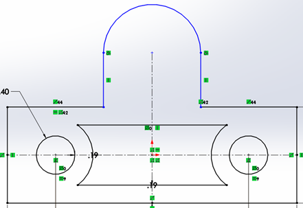
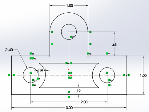
Add a circle to the center of the arc (Figure 3.15). Rather than dimension it, add an equal relation to it between the other two circles. Then add a 0.625” dimension between the center of the arc/circle and one of the upper lines on the rectangle (click the circle on its perimeter and then click the line; click to place the dimension and enter “0.625”). Add a dimension between the left and right vertical lines. Place the dimension slightly above the sketch and then specify 1 inch for the dimension.
Exercise 3.3: Video Tutorial of Upper Clevis Joint Sketch
Here is a video tutorial version of the instructions written above.
Fillet the Corners and Extrude
Fillet all the outside corners to have a radius of .25” and fillet the inside corners to have a radius of .0625”. Activate the Sketch fillet command, specify the radius of .25” in the size box. Click all 6 of the outside corners one by one. Hit the confirm green check mark for the fillet, change the radius in the size box to .0625” and click the 4 inside corners.
The final sketch is shown below again as it was at the beginning of this section.

Activate the Extruded Boss/Base command by switching to the Features tab of the CommandManager (the command is on the very left-hand side). Set the depth to .25” in the property manager as is shown in figure 2.49 and confirm with a green check mark.
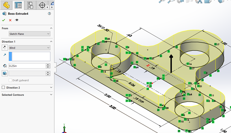
Save your part as 2130003. You have finished this tutorial! Here is the 2130003 Answer Key to check your work.
Exercise 3.4: Video Tutorial of Fillets and Extrude
Here is a video tutorial version of the instructions written above.
