Extruded Features
It has been previously stated that the above features are called Sketch-Based Features. In SolidWorks, feature-based features open many new possibilities for model shapes and increased efficiency in modeling. Feature-Based Features make modifications to already existing features based on common design parameters of the mechanical designer.
Some examples of feature-based features are…
- Pattern Features (Mirror, Linear Pattern, Circular Pattern, etc.)
- Fillet and Chamfer
- DFM Tools (Shell, Draft, Dome, Rib, etc.)
Pattern Features
These features such as mirror, linear pattern, and circular pattern should already look familiar to you from chapter 2 of this text. These options exist in the sketch environment, but there is much more power in applying these types of features in the feature environment than in the sketch environment.
Mirror
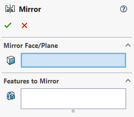
The mirror feature can be used to mirror one or more features across a mirror plane. Sometimes you must create the mirror plane but most of the time, the front, top, or right default plane will do. When you activate the mirror property manager (figure 4.8), you select the features you want to mirror and the mirror plane.
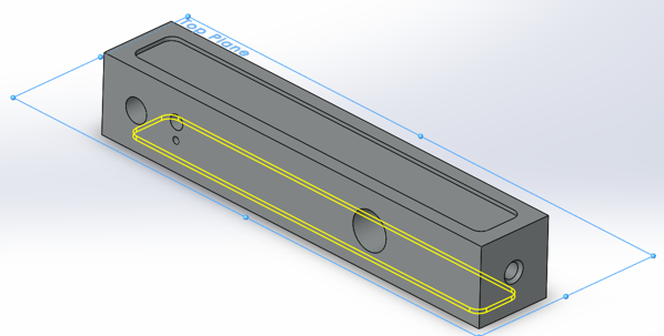
In the example shown below in figure 4.9, the top cut out is being mirrored onto the bottom of part CAE1002 by using the top plane as the mirror plane. For this to work, the main boss extrude needs to be centered about the top plane on creation.
Circular Pattern
Circular pattern is one of the more popular and common features due to the occurrence of patterns in cylindrical parts such as hubs, flywheels, gears, etc. The circular pattern tool is like the sketch pattern tool except instead of selecting a point as the pattern axis, you select a reference axis or feature representing an axis to specify an axis for the pattern. This is because we are working in 3D and to truly define a circular pattern in 3D, we must center the pattern with a 3-dimensional object such as an axis.
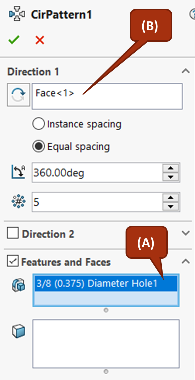
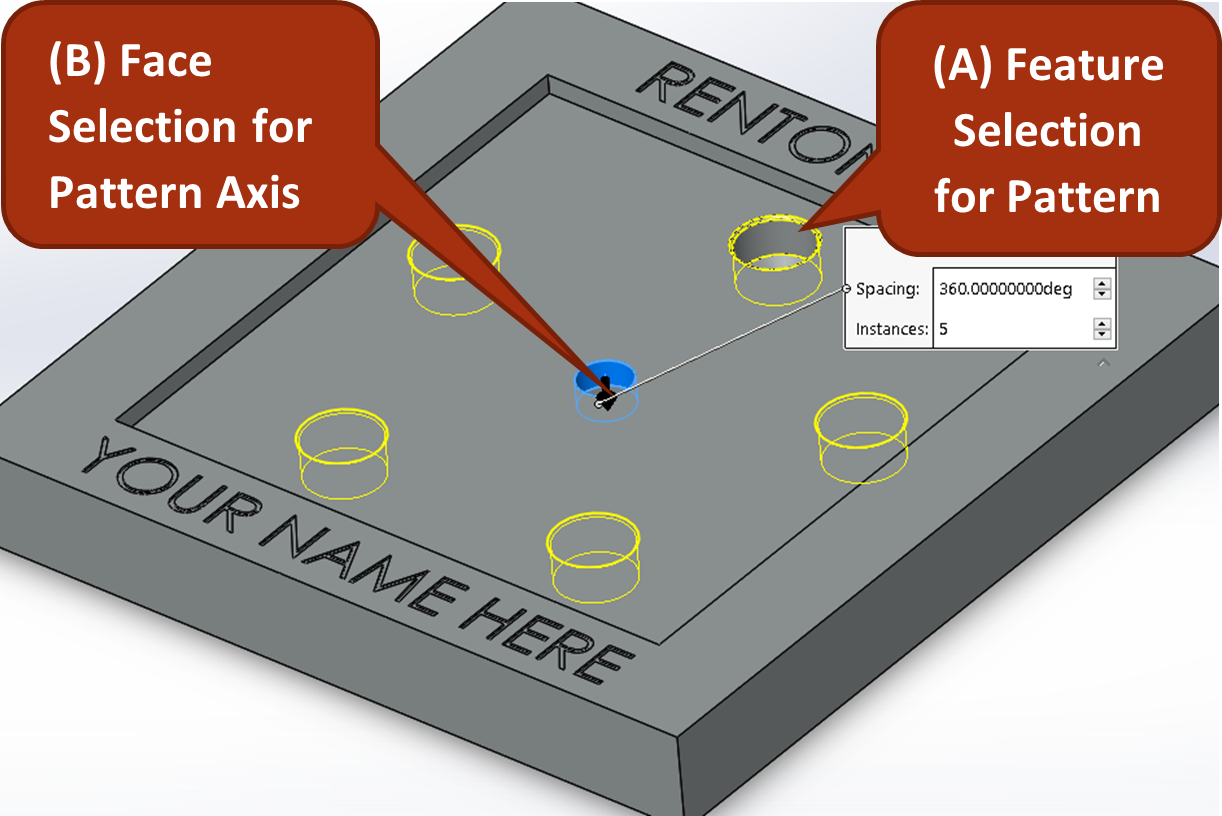
In the example shown in figure 4.11 using circular pattern, when the circular pattern tool is activated, the top 3/8 hole is selected as the feature to be patterned (A) and the center hole in the center of the part is then selected as the reference for the pattern axis (B).
Exercise 4.4: Practice Circular Pattern
Let’s make a circular pattern from the 3/8″ hole on the on the bottom face of the pocket in CAE1001. It’s as simple as selecting the geometry to be patterned with a reference axis such as the center counterbore hole.
- First activate the circular pattern tool from the Linear Pattern drop down on the Features tab of the CommandManager.
- Then select for features to pattern the top 3/8″ hole, also specifying equal spacing and how many holes will be created for the pattern.
- Then select the inner face of the counterbore hole as shown above.
- Specify the spacing and number of instances to be in the pattern.
Linear Pattern
Linear pattern works much of the same way as circular pattern. However, instead of selected a pattern axis, you select pattern directions. You can select either one or two pattern directions. You also have the option of specifying either a number of copies and spacing for the pattern or patterning up to a reference with specified spacing from the reference edge.
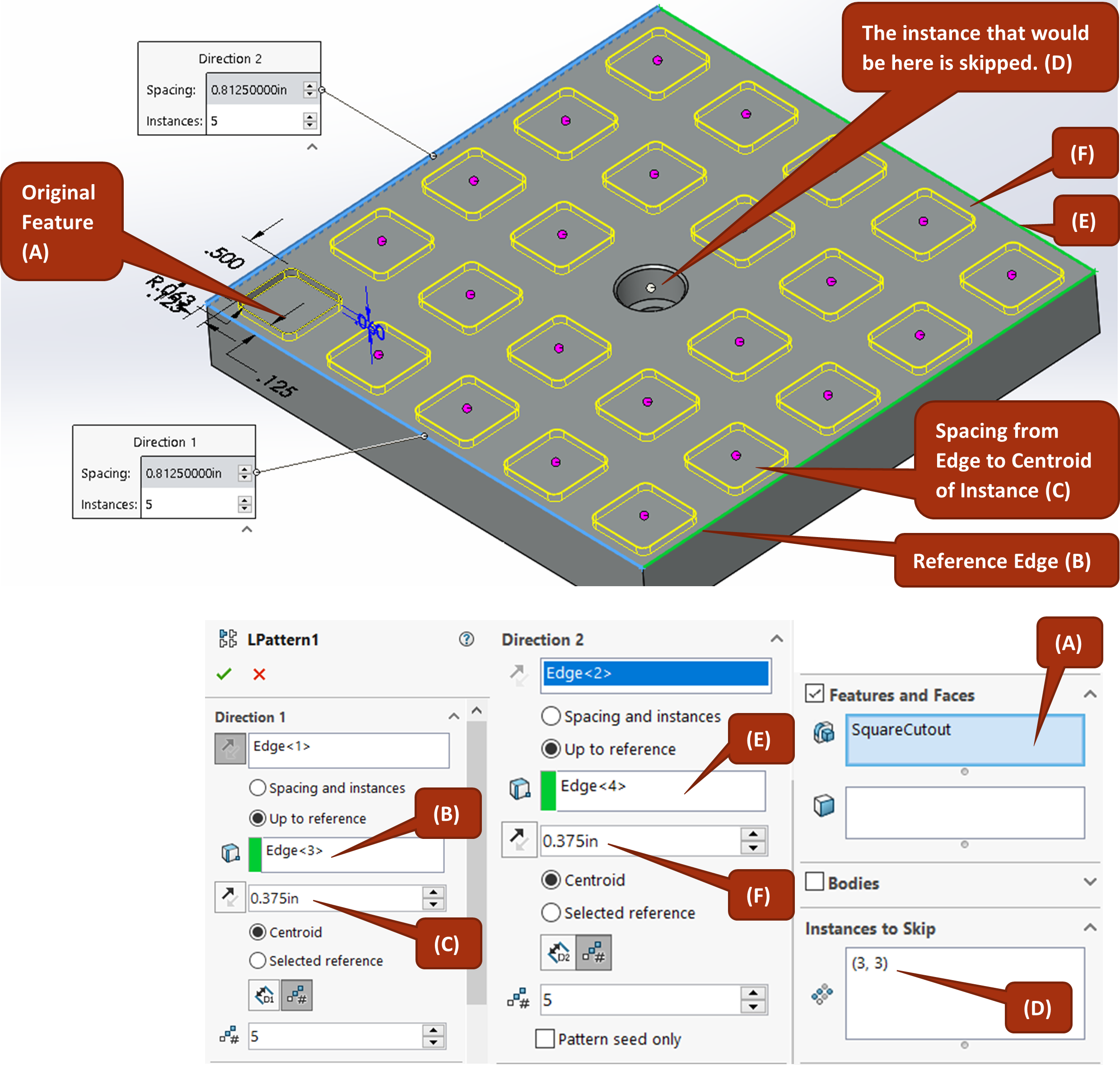
In the example shown in figure 4.12, a 0.5-inch square in the bottom left edge of the part is patterned in the x and y direction. The feature is patterned up to a reference using the opposing edge of the part as the reference for both the x and y. Measurements specified in the property dialog box are from the centroid of the feature being patterned, so .375 inches is specified in the reference offset to give .125 inches of space from the reference edge (same as the originating feature).
The number of instances is then set to five for both directions and the middle instance is skipped to avoid interfering with the counterbore hole that was already there. In this example, because the feature is being patterned to a reference, the spacing between each individual instance is automatically calculated and doesn’t need to be specified.
Exercise 4.5: Using Linear Pattern Feature
Let’s explore all the options available with the linear pattern feature that enable you to specify your design intent. We will see how to use linear pattern with set spacing and instance count, how to pattern up to a reference, spacing from a reference edge on the original instance, and skipping instances.
- Sketch and extrude a cut of a square cutout with fillets built into the sketch on the bottom face of CAE1001.
- Activate the linear pattern feature, select your feature to patter, reference edges for direction 1 and 2, and choose up to reference.
- Choose the opposing edges as the reference edges for direction 1 and 2.
- Choose to space based off a reference edge and choose the reference faces applicable on the original square cutout.
Fillet and Chamfer
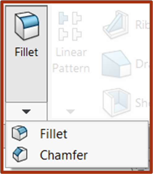
The fillet and chamfer tool are very straightforward and intuitive: you specify the radius or chamfer size you want and then click edges. With fillet and chamfer, you can select edges and faces to create 3D fillets that can’t be done in Sketch fillet or sketch chamfer. In addition, all the fillets and chamfers that are possible with sketch fillet and chamfer can be done using the feature fillet and chamfer.
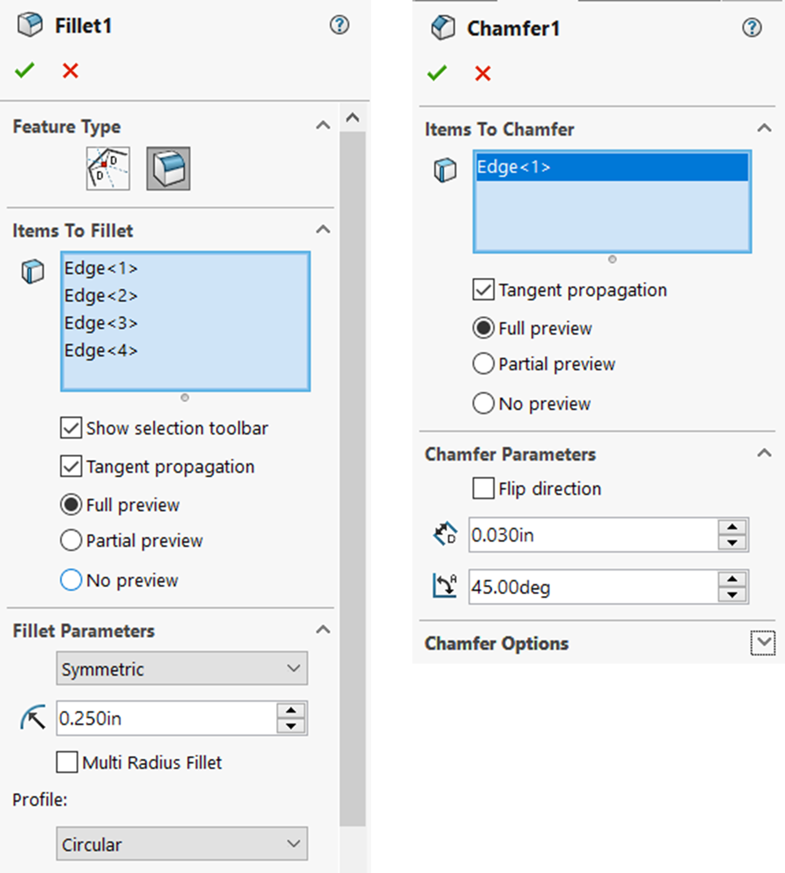
Many designers will prefer to do all fillets and chamfers using the feature fillet and chamfer tool. The fillet and chamfer feature tools will allow you to customize your fillets and chamfers with extreme specificity.
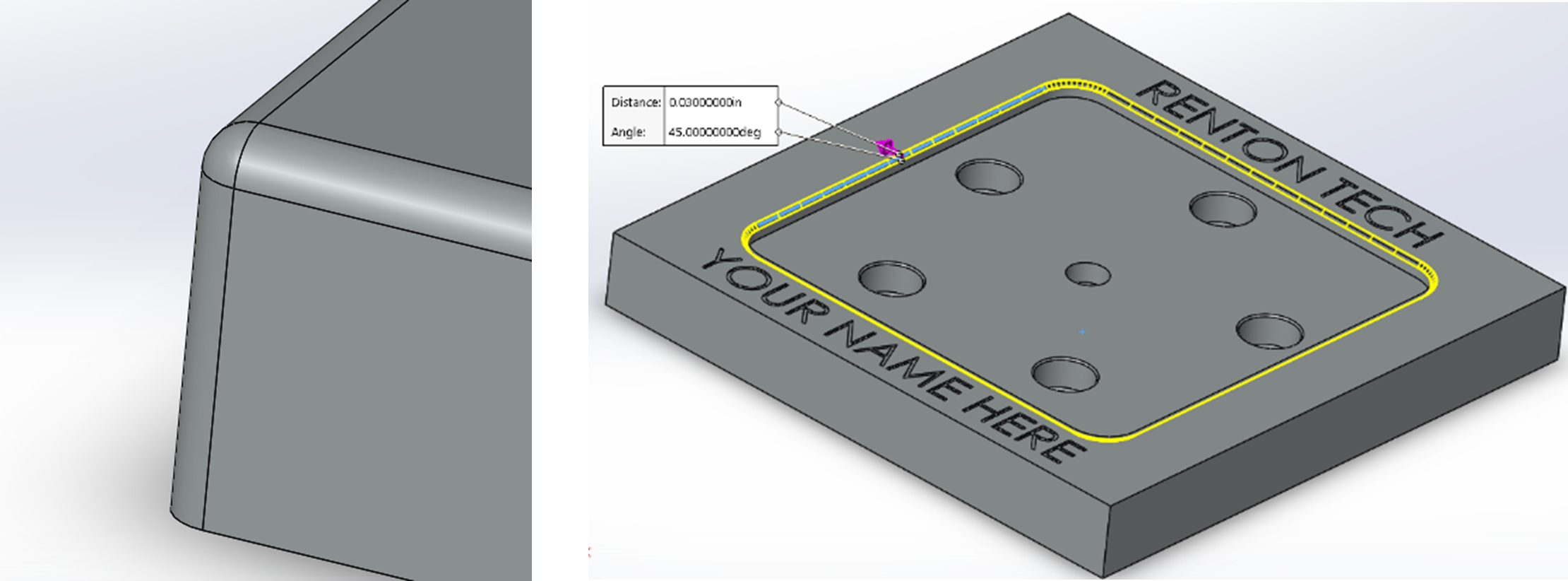
Fillet specifically has a smart context toolbar that allows you to select model elements faster. When you select a singular edge for fillet, the context toolbar appears with options for other edges to automatically select. You can select as many fillets or chamfer of the same size as you want in just one fillet or chamfer feature. You only need to make a new fillet or chamfer feature when you want to change the size.

Exercise 4.6: Fillets and Chamfers
Add the specified fillets and chamfers to CAE 1001 using the fillet and chamfer feature tools.
Working with Multi-Feature Parts
There are editing capabilities that are possible when working with multi-feature parts. Some of the main benefits of this are…
- Being able to reorder features in the FeatureManager Design Tree by left click dragging features.
- Being able to roll back to an earlier stage of the model and add more features at that stage using the Rollback Bar. Left click drag the Rollback bar to adjust model timeline.
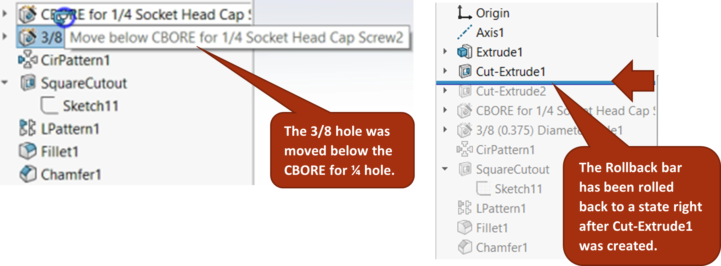
These are important capabilities because many times in the design process, there are design changes that necessitate other features occurring earlier in the model or needing to add foundational features earlier in the model. Without these capabilities of reordering and rolling back using the Rollback bar, you would have to redo all the features that come after the point you need to change.
Exercise 4.7: Rollback and Feature Reorder
One or two features should be reordered in CAE1001. Reorder them so that best design practice is followed with extrudes and base features at the beginning, hole wizard features after, pattern next, and finally fillet and chamfer features at the end of the feature manager design tree. Also, rename each feature so that it has an easily recognizable name.
DFM stands for Design for Manufacturability. There are many feature based tools in SolidWorks that aid the mechanical designer in designing components and assemblies that can be manufactured by common manufacturing processes. Read this Introduction to DFM article for more information.
