Introduction to SolidWorks
The user interface elements that will be talked about in this section are going to be those that have major impact on your modeling capability in the SolidWorks software. These are going to be the elements that you want to pay attention to and get down to ensure you learn modeling well.
CommandManager
The CommandManager is like the ribbon of other programs such as AutoCAD® and Microsoft Office® products (Figure 1.12).

The command manager contains context specific commands based on what type of file you are working in and what you are trying to do. The command manager is composed of tabs that relate to specific functions in SolidWorks. The command manager also looks different based on whether you are creating a new part, assembly, or drawing.
The most common CommandManager tabs you will use are the Features and Sketch tabs. To use commands in the CommandManager, you switch to the tab you desire and then left click the command you are looking for. Descriptions will appear next to your cursor when you hover your mouse cursor over a command. When you activate a command by left clicking on it, the property manager will appear with messages and tips on what to do next.
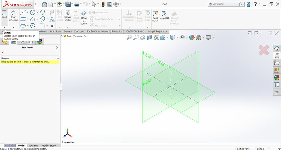
For example, when you left click on the Sketch command in the Sketch tab of the CommandManager, the property manager opens in the manager pane and shows the message, “Select a plane on which to create a sketch for the entity.” The default Front, Right, and Top Planes also highlight and the CommandManager has switched to the Sketch tab (Figure 1.13). Interaction with the CommandManager is dynamic in that when you choose a command, things change in the manager pane, CommandManager, and Graphics Area.
Graphics Area
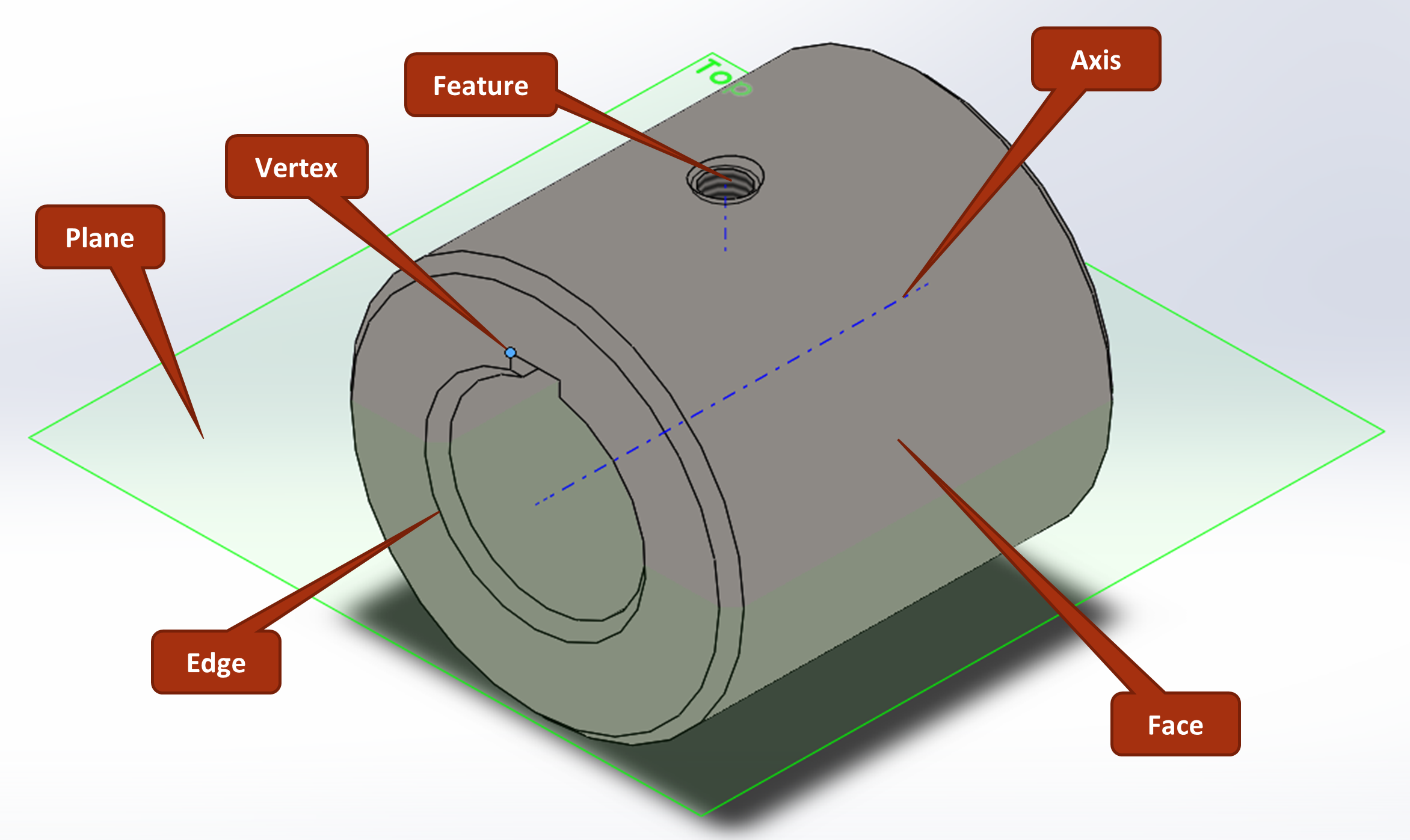
The graphics area is where the model is created and where the user interacts with the model. In the graphics area, you can select vertexes (points), edges, faces, planes, axes, features, and bodies associated with a model (Figure 1.14).
Heads-Up View Tool Bar
The heads-up view toolbar (figure 15) is right below the CommandManager in the Graphics Area and controls how the model looks in the graphics area. You are able to change the display style, change the view orientation (front, right, top, isometric, etc.), hide/show different items, edit the appearance of items, zoom, and create section views of your model.

Manager Pane
The manager pane contains the feature manager, property manager, ConfigurationManager, dimXpert manager (relevant only to model based definition), and DisplayManager as tabs at the top of the pane (Figure 1.16).
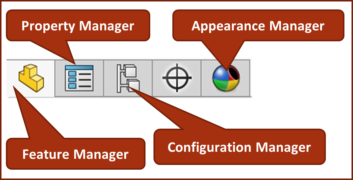
All the tabs can be activated manually. However, the manager pane is dynamic in that it changes to the corresponding tab based on actions you make in SolidWorks®. When a feature or sketch command is activated, the manager pane switches over to the property manager tab; when an appearance command is activated, the manager pane switches to the appearance manager tab. The configuration and dimXpert tabs are only activated when the user manually switches to those tabs by left clicking on them. The feature manager tab is active by default.
Feature Manager Design Tree
The feature manager design tree is one of the most important parts of the SolidWorks® user interface. This is the place where features are managed, edited, suppressed, hidden, etc. When you create a new sketch or feature, it appears in the feature manager design tree in the order in which it was created.
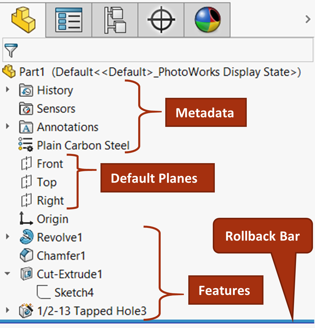
The feature manager design tree holds the features, sketches, reference geometry, the origin of the part, material designation, annotation folders (relevant only to model based definition), sensors, and history of changes (Figure 1.17). The part name always appears at the top of the feature manager design tree along with the active configuration and display state.
The little triangles to the left of the items in the feature manager design tree are called flyouts. You can left click on them to expand or collapse them.
Facts About the Feature Manager Design Tree
- When you left click an item in the feature manager design tree, an in-context toolbar appears next to your cursor with relevant commands.
- When you right click on an item, both the in-context toolbar and a longer list of action options appear.
- Double clicking a folder expands the folder and double clicking a feature shows the feature dimensions.
- Slow double clicking an item allows you to rename the item.
- Doing all these things highlights the respective item in the graphics area (if it exists in the graphics area).
Property Manager
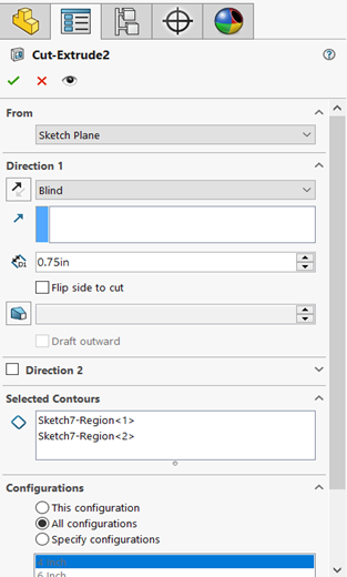
The property manager looks different based off which command is active; even different features have different property managers. The property manager controls the settings of the command that is being executed. For example, if you are extruding a sketch using the Extruded Cut command, you control every aspect of the extrude via the property manager (figure 1.18) such as depth (the thickness of your part profile) and draft angle (how much the thickness tapers).
Exercise 1.4: Using the Interface to Modify the Model
Within your Coupler part, use the Commandmanager, Manager Pane, and Graphics Area to make the following changes to the Coupler model.
- Click on the outer face of the Coupler.
- Change the length to 5 inches and the inner diameter to 1.75 inches by left clicking on the in context dimensions that appear.
- Click on the Cut-Extrude1 feature in the Feature Manage Design Tree and from the Context toolbar, select the Edit Sketch icon.
- Sketch a small circle directly below the keyway on the other side of the Coupler inner diameter so that it intersects the Coupler material. Confirm the sketch. There should now be a new small hole in the Coupler part.
- Click on the Chamfer1 feature in the Feature Manager Design Tree and select the Edit Feature icon from the context toolbar. Change the chamfer size to .1″ and confirm the chamfer.
- From the heads up view toolbar, change the orientation to isometric and create a default section view using the right plane. Then, change the display style to wireframe.
- Toggle between the different zoom options in the heads up view toolbar.
- Also from the heads up view toolbar, turn on the temporary axes and primary plane visibility.
Features in SolidWorks are what make up a 3D model. These are things like extrudes, holes, fillets, rounds, etc.
The sketch tab contains sketch commands that are used to make 2D profiles and shapes that are then made into 3D features.
The display style is a setting that impacts how the model appears in the graphics area (shaded, wireframe, hidden lines visible, etc.)
Section views are views of your model cut in a specific location and orientation. They are useful for evaluating internal components of your SolidWorks part or assembly.
Reference geometry is geometry such as planes, points, and axes that is used for construction of other geometric features but don't actually represent geometry of the model. See SolidWorks Help: Reference Geometry.
different versions of the part/assembly
different versions of how the part/assembly appears
Icons usually in the shape of sideways triangles that expand or collapse sub-items.
