Advanced Sketching Tutorials
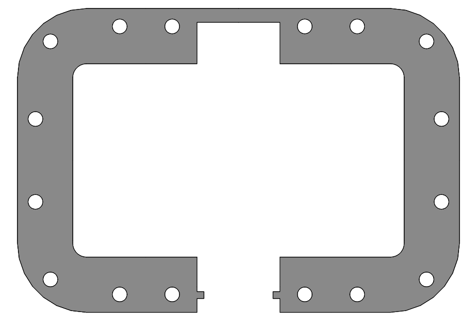
Here let’s step up our sketching practice a bit with a gasket part that requires a significant amount of relations and modification tools. We will demonstrate the sketching of 2130205 Oil Pan Gasket drawing linked.
The Center Rectangle and Offsets
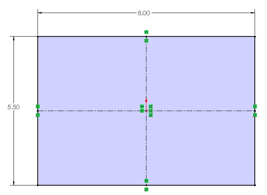
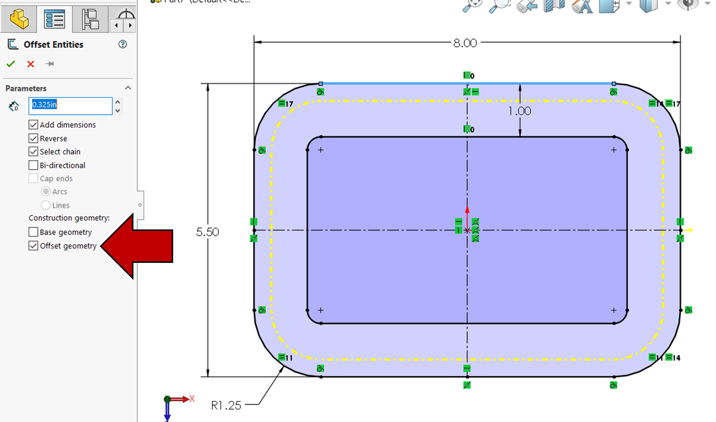
First start a SolidWorks new part with ANSI Drafting Standard and IPS Units and start a new sketch on the Top Plane. Draw a center rectangle at the origin using the From Midpoints option that is 8 inches in length and 5.5 inches in width (Figure 3.18).
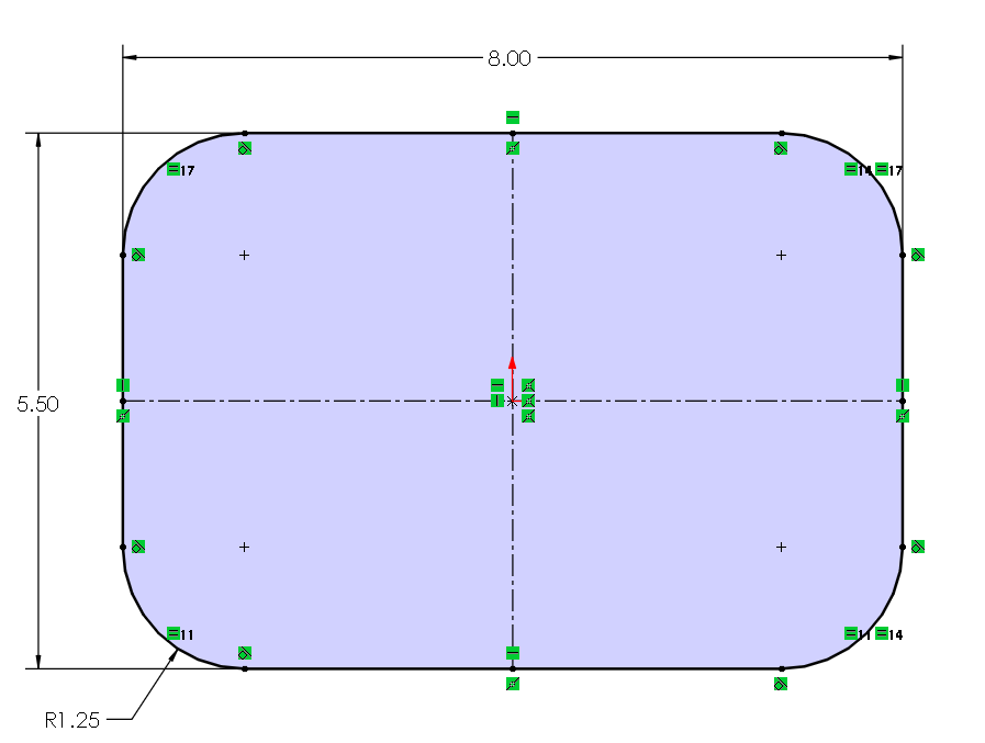
After adding the center rectangle and dimensioning it using the Smart Dimension, use the fillet sketch tool to add 1.25 inch fillets to the four corners of the center rectangle. We are adding the fillets this early into the sketching process because we want to offset the outer contour inward with the fillets using the Offset Entities tool.
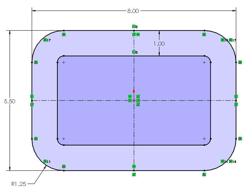
Using Offset Entities, offset the rectangle inward by 1 inch making sure that Select Chain is checked. Click on one of the edges of the outer contour and with Select Chain enabled, the offset entities tool will collect all the connected edges of the contour. Note that a 1 inch dimension is automatically added.
Use Offset Entities again to offset the outer contour by .325 inches as construction geometry. To make the offset geometry construction geometry, under Construction Geometry in the property manager, activate the Offset Geometry option.
Exercise 3.5: Video Tutorial of Filleted and Offset Rectangles
Here is a video tutorial version of the instructions written above.
Creating the Cutouts
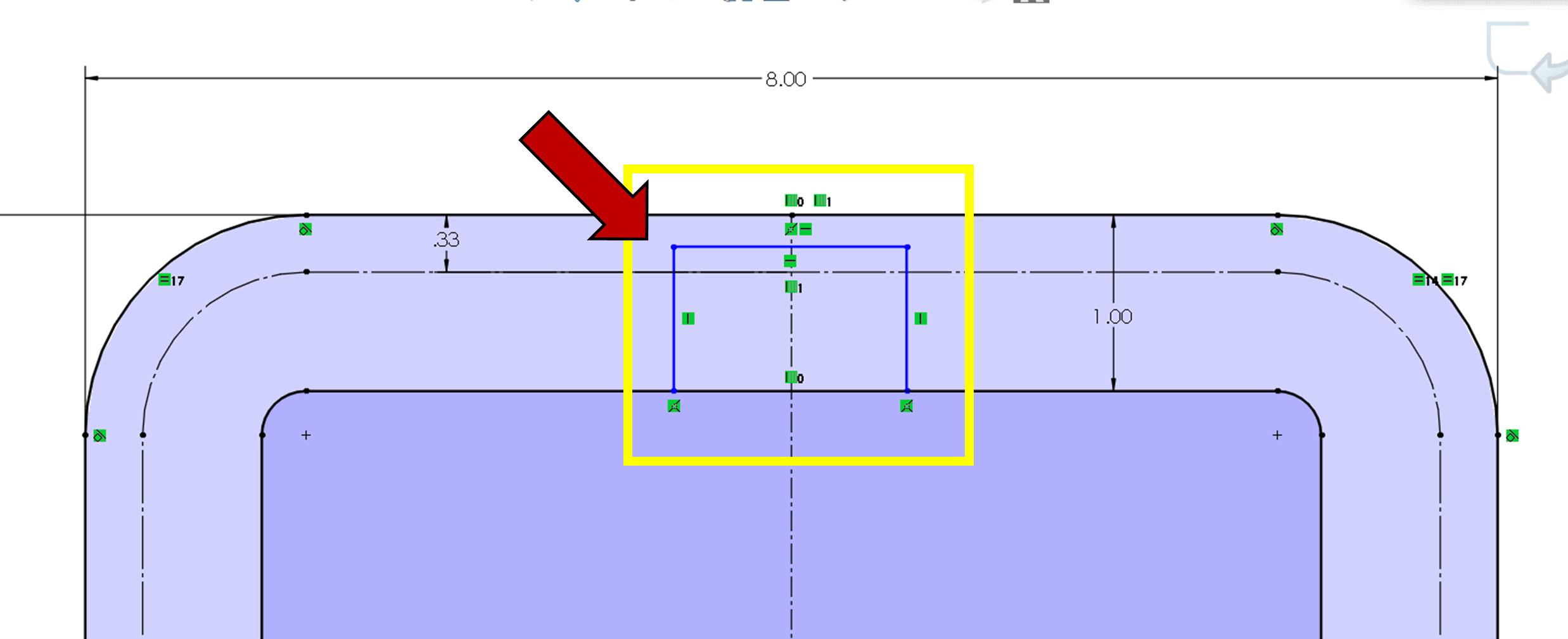
Using the Line tool, draw a rough sketch of the top middle cutout making sure to add the automatic coincident relations to the inner contour (Figure 3.22).
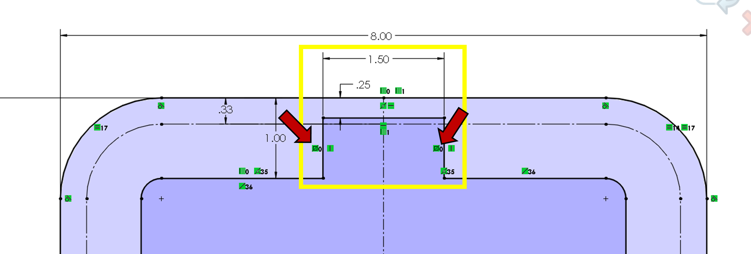
Trim away the excess lines making sure not to trim the vertical centerline. Fully define the cutout with a 1.50 inch length, .25 inch thickness from top edge, and by making the left and right edge of the cutout symmetric with the vertical centerline (Figure 3.23).
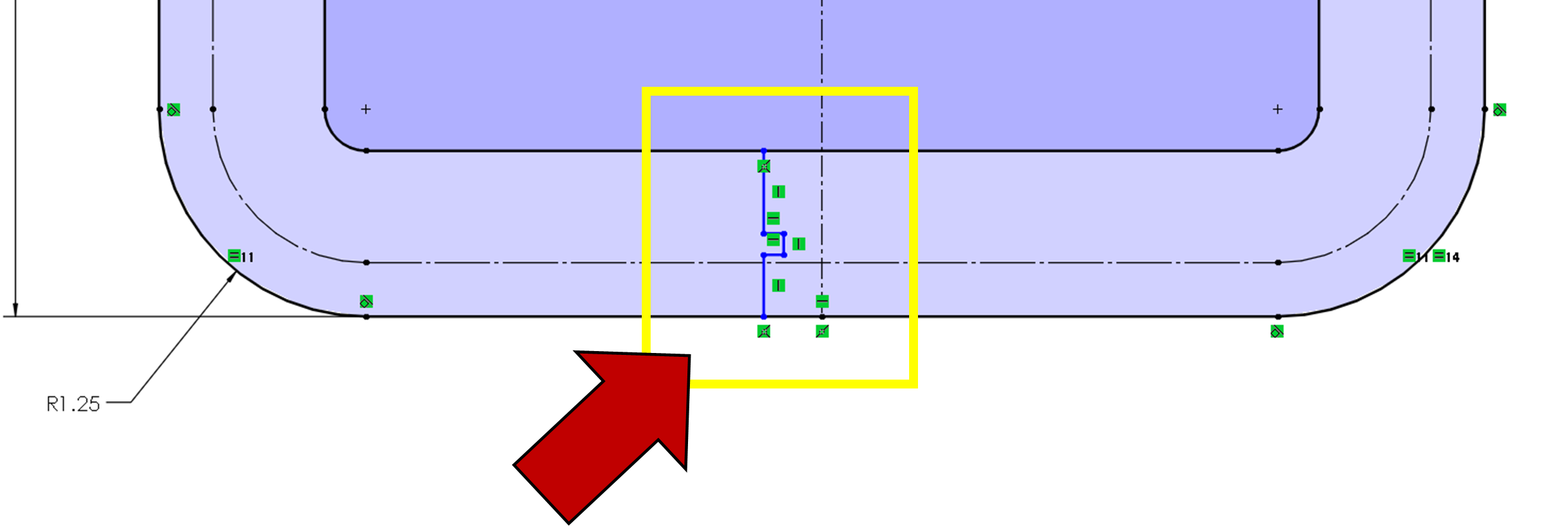
Draw a rough sketch of the bottom left side of the cutout (don’t do the right side because we will mirror it over). Make sure that your end points automatically have coincident relations with the inner and outer contour (Figure 3.24).
Mirror the left side to the right side using the vertical center line and then trim the excess lines away making sure not to trim away the vertical centerline (Figure 3.25). You will also need to make the endpoint of the vertical centerline coincident with the bottom outer contour edge or draw a construction line connecting the outer contour at the bottom and then making the vertical centerline endpoint midpoint related to the new construction line.

After making sure that the trim was successful and adding the coincident relation was successful, fully define the bottom cutout with a 1.5 inch spacing, 1.25 inch spacing on the tabs, a .25 inch distance from bottom edge on the outer contour to the bottom edge of one of the tabs, a tab thickness of .125 inches and a colinear relation between the left aligned lines of the cutout (Figure 3.26).

Exercise 3.6: Video Tutorial of Creating the Cutouts
Here is a video tutorial version of the instructions written above.
Clearance Hole Placement
The clearance holes in the Oil Pan Gasket are symmetrical across both the vertical centerline and the horizontal centerline. So, we only need to create and fully define the holes in one quarter of the part and then we will mirror the holes across the vertical and horizontal centerlines.
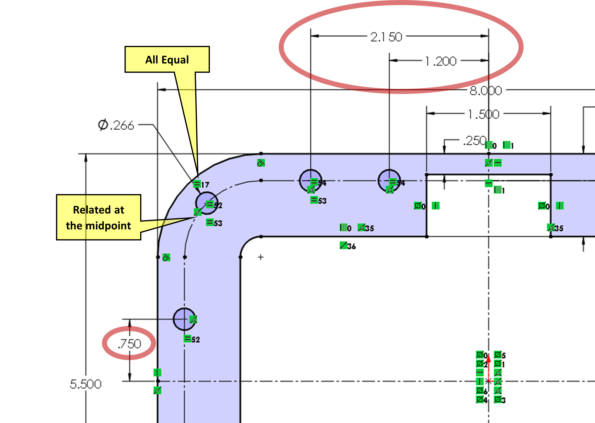
Using the Circle tool, place and fully define four .266 inch diameter holes as shown in figure 3.27. The right most hole is dimensioned from the vertical centerline by 1.200 inches, the second to right most hole is dimensioned from the vertical centerline by 2.15 inches. Make the four holes equal by CTRL selecting all four holes and choosing the equal relation. The hole at the fillet corner is coincident with the midpoint of the fillet on the construction offset; this can be added automatically by snapping to the construction arc’s midpoint. The left most hole is .75 inches from the horizontal centerline.
When clearance holes are fully defined in the top left corner of the sketch, use Mirror Entities to first mirror all the clearance holes across the vertical centerline and then use Mirror Entities a second time to mirror all eight holes across the horizontal centerline. You will see a lot of symmetry relations crowd the drawing now (Figure 3.27).
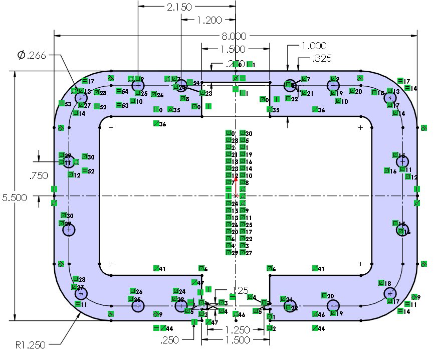
Use the Extruded Boss/Base feature to extrude the sketch .005 inches and save as 2130205.
Exercise 3.7: Video Tutorial of Clearance Holes and Extrude
Here is a video tutorial version of the instructions written above.
