Sketching and Relations
The sketch tools within SolidWorks® are very similar to those in other CAD and Parametric programs: line, circle, rectangle, polygon, slot, arc, etc. (Figure 2.10). Each command also has drop down options to allow you to have more control over how you specify a geometric element in a sketch. There are yet even more customizing options for each sketch tool in the property manager for that sketch tool.

As soon as you activate a sketch tool by left clicking on it from the CommandManager, the property manager for that sketch tool opens, usually with a set of illustrative directions for how to use the sketch tool.
These tools are going to be the most straightforward tools because they work the same across all platforms (for the most part). However, as you add sketch geometry to a sketch, often times sketch relations will be automatically added to the origin and the entities you are adding. We will discuss these more later in this chapter and how to use them but for now just be aware that you will see them appear on your sketch as green tiny boxes.
Design Intent in Sketching
SolidWorks called the Sketch tools “Sketch” for a reason: the intention behind parametric design is to do a rough sketch of what you want first, and then constrain it using dimensional (Smart Dimension) and geometric (Relations) constraints. This will allow you to model way faster than if you tried to get all the details right as you sketched. Sketching this way also ensures that you are modeling based on design intent, not putting any unnecessary constraints on the geometry that are not needed for the design to function. An example is shown below in figures 2.11, 2.12, and 2.13.
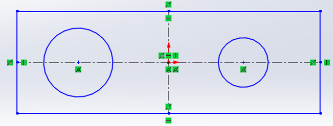
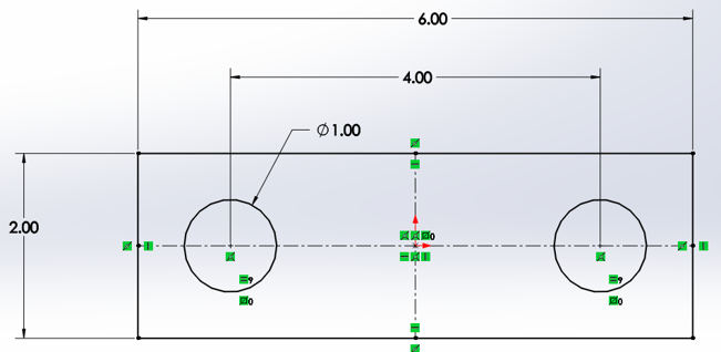
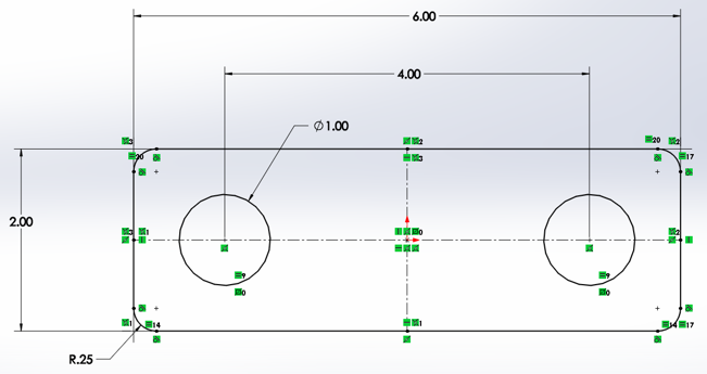
You will notice that the sketch in figure 2.11, 12, and 13 started out as blue and then, constraints were added, it turned black. When features/entities are blue in the sketch environment, they are under-defined. When features/entities are black in the sketch environment, they are fully defined. These states are known as sketch geometry status’.
When a sketch is fully defined, all the appropriate design criteria needed to manufacture the feature(s) has been specified by the designer. When a sketch is under defined, this means that there is not enough information, not enough design criteria specified in the sketch environment to manufacture the features drawn.
Look at Figure 2.11 again: without the dimensions on the geometry to specify the intended size and location for the drawing, how would manufacturing know what the design intent was for the part? Without the symmetry constraint on the two circles between the vertical center line, how would manufacturing know where one hole is supposed to be with respect to the rest of the part? Yes, the information is in the model, but there is variation in manufacturing processes no matter what process it is, so what do we compare the manufactured parts to if there is no design information in the model? Therefore, it is critical to make sketches fully defined before sending them downstream in the product design process.
Line
When you activate a tool, such as the line tool, you specify the location of the base point with a left click and then the size and orientation with the second left click; to exit the line command, simply right click and select “Select” or click the green check mark (Figure 2.14). Many sketch creation tools have expanded options. The line command has a midpoint option where you can specify the midpoint of the line on your first mouse click as opposed to the first endpoint.

Exercise 2.2: Using Line
In this exercise, let’s take some time to practice the line sketch creation tool, study its property manager, and experiment with the different options.
Rectangle and Circle
The rectangle tool also allows you to either specify rectangles using two corners, the center of the rectangle, or 3 corner points. Below is an example of using the center point of the rectangle as the base point:

The property managers of all the sketch creation tools have many options and instructions on how to use each option. All sketch tools allow you to convert the sketch entities into construction geometry (also known as reference geometry). The rectangle tool specifically has different options for how the construction lines that help constrain the rectangle are placed: at the corners or at the midpoints (Figure 2.16).
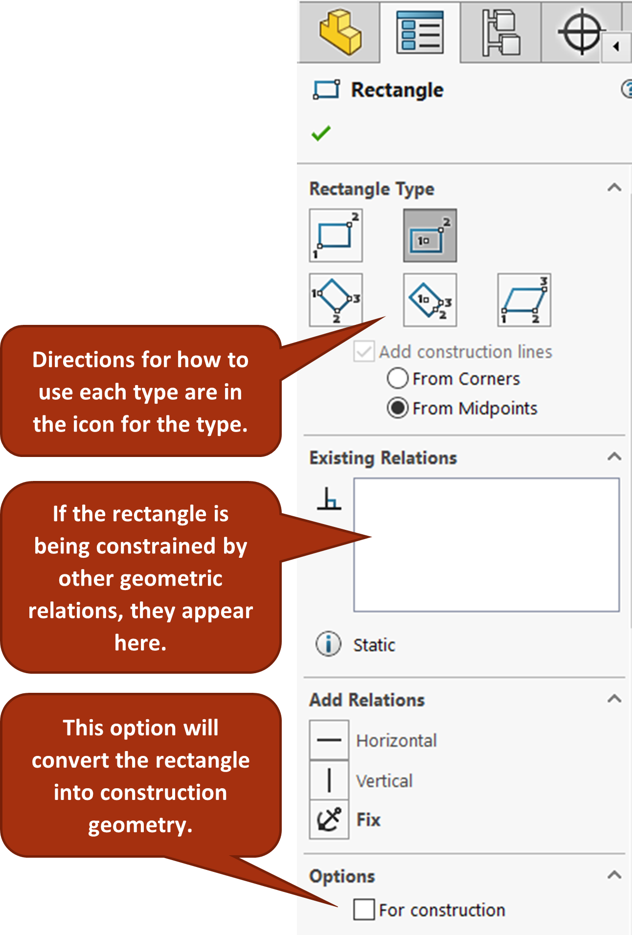
In Figure 2.16, you can see that in the rectangle type icons, there are number 1, 2, 3. These indicate the order in which you left click to specify those points indicated in the icons.
Exercise 2.3: Using Rectangle and Circle Sketch Tools
In this exercise we will practice using the rectangle and circle sketch tools, exploring their property managers, and experimenting with the different options.
ARcs, Slots, Polygons and Ellipses
The other sketch commands work in a very similar fashion as the line and rectangle commands. It is important to practice each sketch command, study each property manager for each sketch command, and try different variations of using the sketch commands to build proficiency in them.
Exercise 2.4: Arcs, Slots, Polygons and Ellipses
Slots, polygons, and ellipses involve a bit more action with their commands to get them into your sketch. They still have similar behavior to the sketch creation tools we have just explored though. Spend some time practicing these sketch creation tools.
Fillet and Chamfer
Entity based sketch tools such as fillet and chamfer allow you to quickly add complex but common sketch entities by modifying sketch entities you have already created. For example, if you’ve already drawn a rectangle using the rectangle tool, you can activate the sketch fillet tool, specify a size in the property manager, then click the corners you want to add fillets to (Figure 2.19).
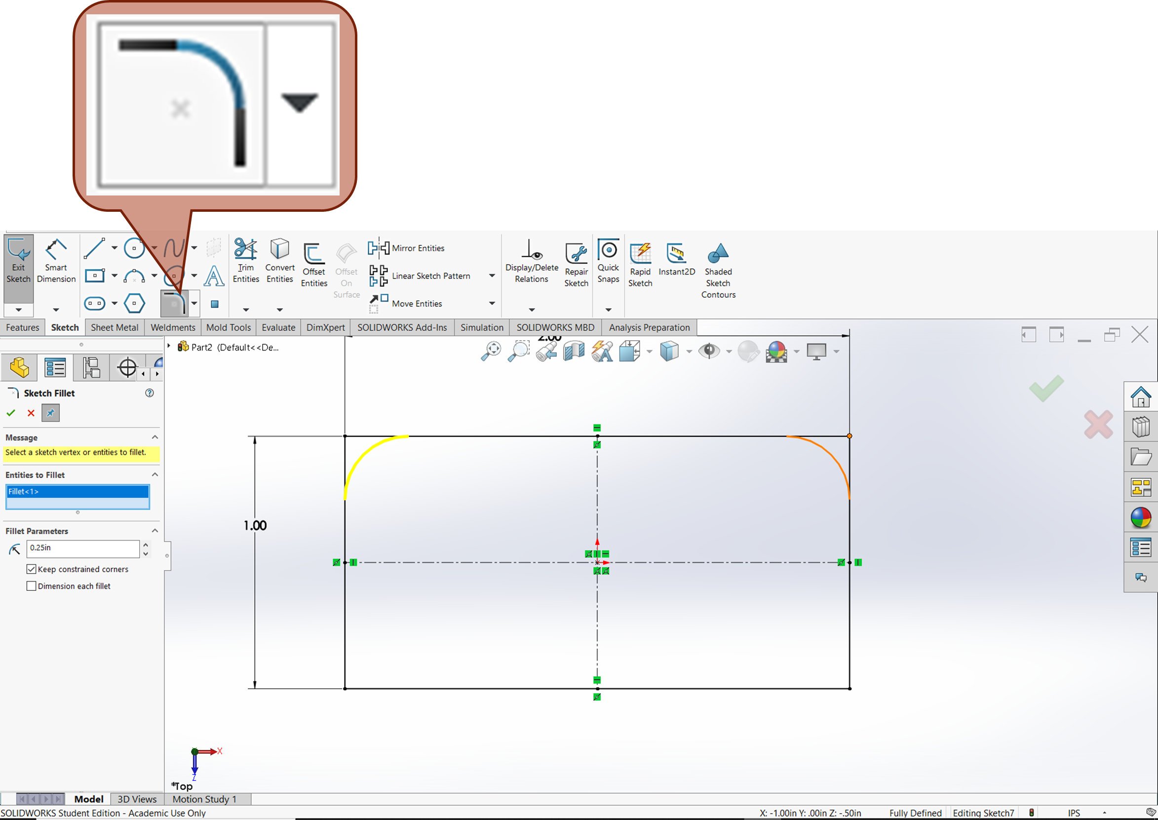
Exercise 2.5 Fillets and Chamfers
Fillets and chamfers are a sometimes useful entity-based sketch creation tool especially when there are other features that need to be added that are related to the fillet or chamfer. Let’s practice using the fillet and chamfer tool to become familiar with how it works.
Computer Aided Design software. SolidWorks, AutoCAD, and SketchUp are examples of CAD software.
Sketch relations constrain sketch geometry geometrically as opposed to dimensionally. Some examples of geometric constraints are parallelism, perpendicularity, tangency, and alignment. Some sketch relations are automatic and others must be added manually in SolidWorks. See SolidWorks Help: Sketch Relations for more information.
Design intent refers to the geometric constraints that the mechanical designer intends for the model to have. For example, a designer can intend for a hole to be in the center of a plate and constrain it as such in the model. See More on Design Intent.
A sketch geometry status that indicates there are not enough design parameters constraining the sketch geometry to allow only one possible condition. See Sketch Geometry Status'.
A sketch geometry status that indicates there is enough design parameters constraining the sketch geometry to allow only one possible condition. See Sketch Geometry Status'.
Sketch geometry status' indicate the condition of constraints on a geometric entity in a SolidWorks sketch. There is under-defined to indicate too little design specification, fully-defined to indicate there is enough design specification, and over-defined to indicate too much design specification (conflicting design parameters). See SolidWorks Help: Sketch Geometry Status' for more information.
Also referred to as reference geometry is used to aid the definition of of geometry that will become part of the final part. Reference geometry isn't anything you will see in the final part, it is a part of the design parameter/constraint that will drive what you see in the final part. See SolidWorks Help Construction Geometry for more information.
