Assembly Modeling
Advanced mates allow you more control and more specified constraints for constraining parts to other parts. The main ones here are Width and Limit mates. There is also symmetric, linear coupler, profile center and path mates here. They work very similar to standard mates, they are just more options and more selected entities to use them.
Width
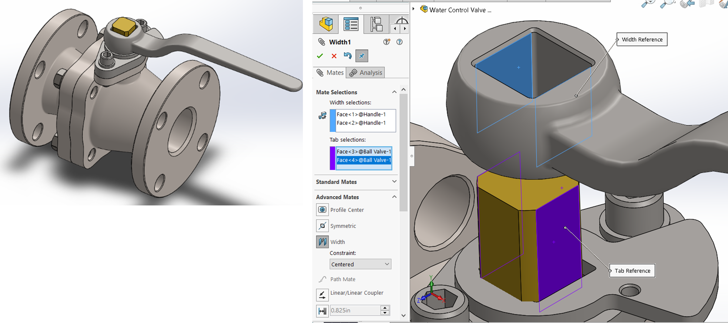
A Width Mate is used to center parts within other parts using planar faces. If you think about it, width does the same thing concentric does but for prismatic parts as opposed to cylindrical parts.
To use width, you select the two faces a part will be centered between and then the two faces you will use as the centering reference on the part you want to center. Use width when default planes and coincident wouldn’t be appropriate (most the time we center parts in relation to the default planes so we can just use them as opposed to width).

Limit Distance and Angle
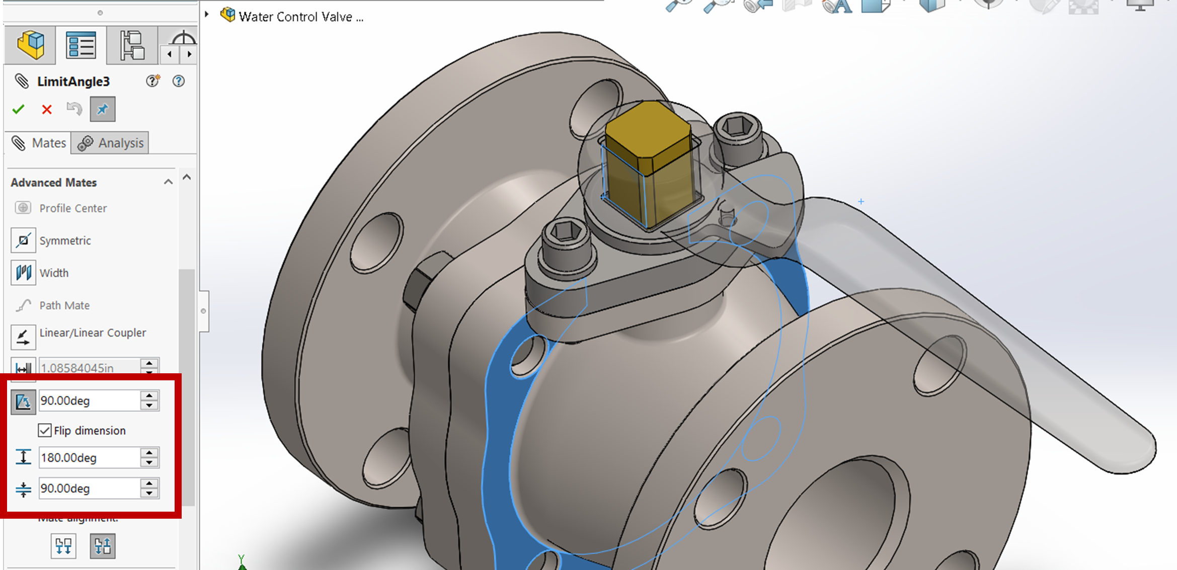
Limit distance and angle mates work just as the standard distance and angle except you can put in a range rather than a single value. This is great for making assemblies dynamic: dynamic hydraulic cylinders or valves or actuators. You specify your minimum and maximum distance/angle and the faces that distance/angle will be between.

Mechanical Mates
Mechanical mates are also available for more specific mechanical relationships between parts such as screw/thread mate (a part turns as it is translated along another part), gear mate (as one part turns at one speed, another part turns at a different speed), rack and pinion, cam, slot, hinge, and universal joints. We won’t get into these here but you can look them up in more detail from SolidWorks Help as well as from MySolidWorks Training on Mechanical Mates.
Exercise 7.5 Advanced and Mechanical Mates
In this exercise, you will be given the opportunity to explore advanced and mechanical mates through the MySolidWorks portal. Below are two training lessons that you can follow along with to explore the two mate categories.
Width mate refers to positioning a pair of planar surfaces centered between another pair of planar surfaces. See SolidWorks Help: Width Mate.
Instead of setting a distance or an angle, you can specify a limit that the part is free to move within. See SolidWorks Help: Limit Distance and Angles.
Mechanical mates are a category of mates that match the interaction and behavior of mechanical components such as gears, cams, hinges, slots, screws, and universal joints. See SolidWorks Help: Mechanical Mates.
