Assembly Modeling
The Design Library is in the task pane and has a link to the SolidWorks Toolbox which is included with most versions of SolidWorks. The design library is filled with common components used in mechanical design and that are commonly sold by suppliers. The most common use of the design library is for fasteners such as screws, bolts, nuts, set screws, washers, etc.

SolidWorks introduced a tool called Smart Fasteners years ago to try to make the fastener specification process faster, but it still holds many bugs. It is only best to use this tool when adding more than a dozen fasteners.
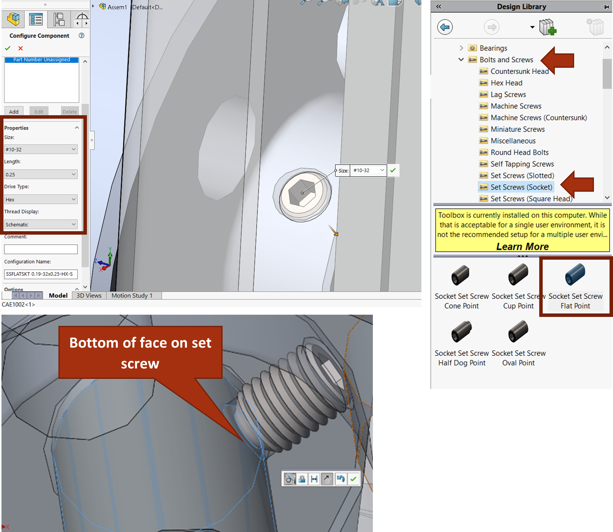
To add fasteners from the SolidWorks toolbox, open the task pane, find the fastener you want to add, and drag and drop it where you want it. Automatic mates will be added if you select a compatible edge. Once you drop the fastener, you can specify all the type settings. Once confirmed, you can add more of the same type of fastener. This feature is great for common fasteners, but if you need specialty fasteners, use models from a common supplier website such as McMaster-Carr.
Exercise 7.6 Specifying Fasteners in CAE1000
In this exercise, you will add a few of the many fasteners that are contained within CAE1000. The rest you will add in the upcoming tutorial. To add the fasteners, you will load the design library and drag components into place. You may also need to add applicable mates to constrain the fasteners to the assembly according to design intent.
- First Add CAE1009 with appropriate mates.
- Load the design library from the Task Pane.
- Add a 1/4-20 Socket Head Cap Screw to the 1/4 counterbore hole at the bottom of the assembly. Make sure to drag over the inset edge of the counterbore so that automatic coincident and concentric mates are added.
- Add a 5/16-18, 3-inch length and 7/8-inch threaded length hex bolt to the body.
- Add the 5/16″ Plain Type A Washers and 5/16-18 Hex Nuts assembled with CAE1008.
- Also add the #10-32 by .25” length set screw to the flywheel tapped hole and make the bottom face of the set screw tangent with the crankshaft.
- #10-32 by .375-inch length set screw between CAE1002 and the hex bolt.
- Add the remaining fasteners and parts to the assembly.
The design library contains many default standard parts that can be used in mechanical design in SolidWorks. You can also add your own standard parts to the design library. See SolidWorks Help: Design Library.
