Assembly Modeling
Up to this point, we have discussed creating SolidWorks parts that can then be used to create assemblies. Assembles are just that: parts that are put together in a specific way. The world’s mechanical products are made up of assemblies. Cars, boats, planes, construction equipment, game systems; these are all made up of assemblies. In this chapter, we will learn how to not only model assemblies from SolidWorks parts, but also explore how to evaluate and document assembly designs.
Learning Objectives
The purpose of this chapter is to…
- Model fully defined assemblies using standard and advanced mates.
- Use interference and collision detection to identify potential problems in an assembly.
- Use exploded views, Bill of Materials, and other notes to document assembly geometric and non-geometric metadata.
- Consolidate design files into a single data package that can be used as the design authority for a mechanical product.
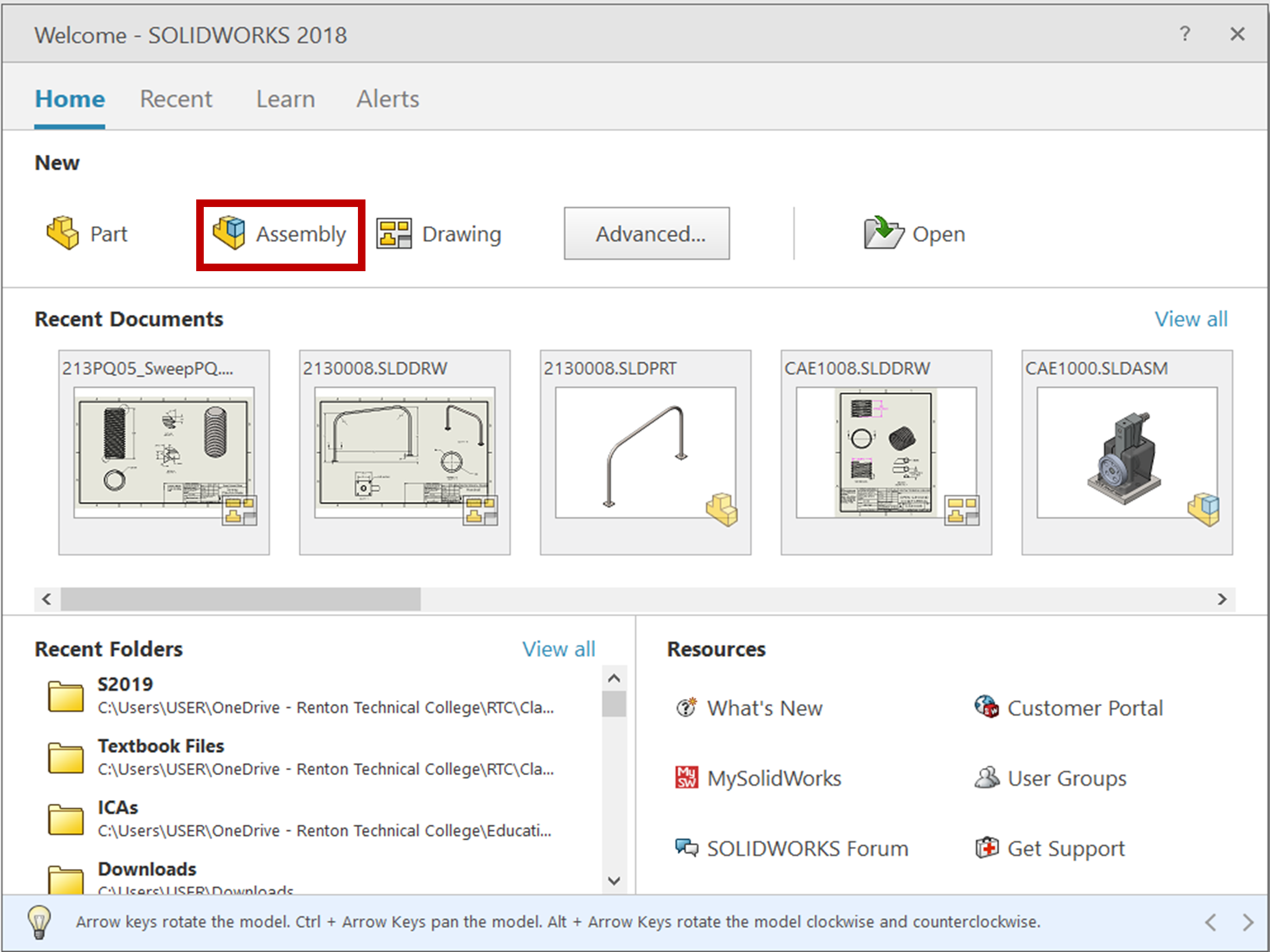
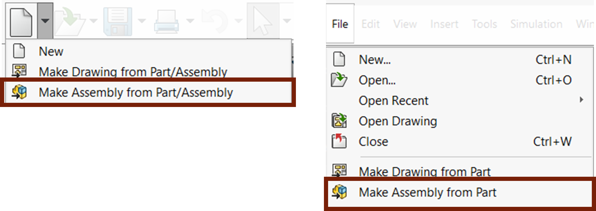
Assembly models are just another type of SolidWorks file. You can start a new assembly file when you start SolidWorks from the Welcome Dialog box or start a new assembly from an open part, just as it is with SolidWorks drawings, by going to the New drop down on the standard toolbar or menu bar and selecting “Start New Assembly from Part”.


There are a couple things to note about the User Interface that are different in SolidWorks assembly files. You still have the CommandManager, FeatureManager, and Property Manager. They all work the same as they do in parts. However, there are different tabs and commands in the CommandManager that are more relevant to assemblies. In the FeatureManager Design Tree, you will see a list of the parts in your assembly, and all their feature manager design trees, as well as a Mates folder showing all of the mates in the assembly.
Mates are the SolidWorks term for part constraints. They are how one part will constrain to another, much like the sketch constraints/relations you are used to. See SolidWorks Help: Mates.
