Constructs Dimentional Floor Framing
Chapter D1– Constructs Dimensional Floor Framing
Topic 1 – Describe Beams and Supports
Methods of Floor Framing
There are two types of methods used to frame floors and connect them to the foundation: Box-Sill and Joist-Embedded. There are also two types of wall framing: Platform and Balloon.
 Box-sill floors are connected to a foundation after it has been poured and set (see figure 1). The floor system sits on a sill which is attached to the top of the foundation wall by anchor bolts. Because the sill is attached after the foundation is placed, it is also compatible with unit masonry foundations. This method can be used with either platform or balloon framing. While this method allows earlier placing of concrete, there is no floor to provide as a working surface until it is set. It does, however, allow for easier placement of a continuous air/vapour barrier.
Figure 1: Box-Sill Method
Joist-embedded floors are only able to be used in concrete foundations and platform framing. The floor system is constructed on the foundation forms which are poured after the floor is framed. The rim joist, end joists, and blocking at the joist ends acts as the concrete forms. An extra joist is required in this system to act as a form at the ends. This allows easier levelling of a floor system as it can be set in place precisely and then poured in place. This method was more common when concrete was wheelbarrowed to wall forms as it provided a working surface when placing concrete. It is now a very rare method of floor framing.
Sills
In box-sill floors, the sill provides both a bearing and nailing surface of the floor system. It is usually a 2×4, 2×6, or 2×8 which is held in place be pre-set anchor bolts and acts to transfer both the live and dead loads of a building to the foundation.
A properly placed foundation should be level. In these cases, the sill may be directly attached to the foundation wall with either a bead of caulking, mineral wood, or foam gasket placed underneath. In the event the foundation is not level, the sill should be laid in a bed of mortar to achieve a consistent level. Joints in the sill should not be placed over openings in the foundation.
Beams and Bearing Walls
Most floor systems are not capable of spanning the entire width of a building and require an intermediate support. To provide this support, beams or load bearing walls are used with columns that are supported on independent footings.
Beams may be constructed of either wood or steel. Steel beams commonly come in two shapes: S beams and W beams. They are designated by shape, height, and weight per lineal measurement (see figure 6 below).
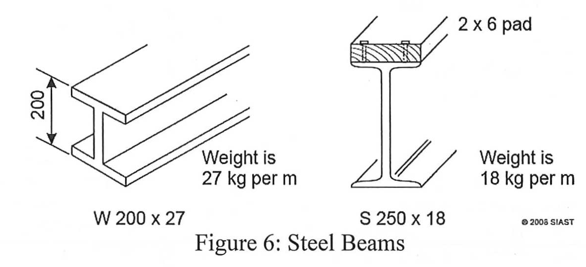
In this image, there are two examples of each steel beam, both in metric measurements. The beam on the left is labelled W 200 x 27. The letter W indicates its shape whereas the 200 indicates its height in mm and the 27 indicates it weighs 27 kg per meter of length. Beams may also be labelled in imperial measurements. For example, a beam labelled S 12 x 27 would indicate an S beam that is 12” in height that weighs 27 lbs. per foot of length. The values vary from beam to beam however, the units used remain the same depending on which system of measurement is used.
There are three types of beams that are constructed of wood: solid, built up, and glue-laminated. A solid beam is simply a piece of timber of sufficient strength to carry the loads. Built up beams are the most common and are typically made from fastening nominal lumber face to face. Glue-laminated beams are a manufactured wood product that is discussed in more detail in the Block A module.
Bearing walls can also be used as an intermediate support for a flooring system. They are supported on a continuous strip footing. They must be framed with a minimum of 2×4 lumber 16” O.C. Much like exterior load bearing walls, they must also have a double top plate. They are also equipped with blocking between each stud space or sheathing to prevent sideways buckling.
Determining Sizes of Built-Up Beams
There are 5 factors which determine the size of beam required for a building:
We will use the following building to determine these factors, some of which are directly given:
Span of The Beam
The beam span is determined by calculating the post spacing. To do this, we need to subtract the foundation wall thickness (x2) from the building length, this is known as the clear span of the beam. That value is then divided by the number of spaces (number of posts + 1). For example:
- This value of 3.52 m is used directly in the span tables found in the NBC
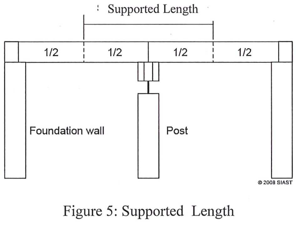 Supported Length
The supported length refers to the length of the floor system that is supported on the beam. It is calculated by taking the span of the floor system and dividing it by two. In the NBC, the floor system span is measured from inside of supports to inside of supports. This would mean we should subtract the width of the sills from the floor joists. If this is not given, as in this example, we will simply use the width of the building.
While the beam is often centered in a building, the supported length is NOT affected by any offset. If the beam is offset by one meter in this example, the supported length will still be 6 meters. This is because the beam is considered to support half of the joist span each way.
Using the NBC Span Tables for Built-Up Wood Beams
There are three tables used for built-up beams in the NBC which are chosen based on how many floors are supported. In this case, one floor is supported so we will use Table 9.23.4.2-H. Find the species in the left-most column and the grade in the next column. Continuing right, we will find a supported length equal or greater to (never less) than 3.52 m. Looking beside hemlock fir #1, we find 3.6 m is the closest value without going lower. We will then continue on that line to find a span equal to or greater than 3.52 m. In this table, that value is 3.82 m which satisfies our requirements.
The columns in the beam span tables are organized by the beam size. If we look to the top of the table, we find that the value of 3.82 m is beneath 5 – 38×235 which indicates that a 5 ply 38 x 235 (2” x 12”) beam is required for this building.
***Try the following example:
- Two story house 10 m x 20 m
- Species used: SPF select structural
- 5 posts
- 250 mm foundation
Constructing Built-Up Beams
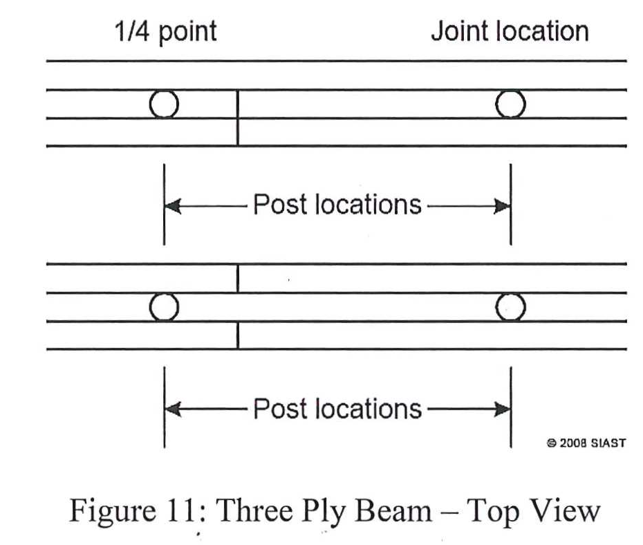
The most important consideration to make in determining the layout of the plies in a built-up beam is locating the joints. Section 9.23.8.3 of the NBC dictates where joints are acceptable and can be summarized in the following:
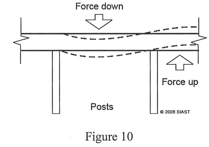
Quarter points are determined by finding a quarter of the distance between posts. For example, if we have a post spacing of 3.52 m, the quarter point would be placed 3.52 m ÷ 4 = 0.88 m from the posts. Quarter points work by using the downward force on the far side of the support which cantilevers the short side of the member that is jointed at the quarter point:
***Find what is wrong with the joint placements in each beam.
Nailing Built-Up Beams
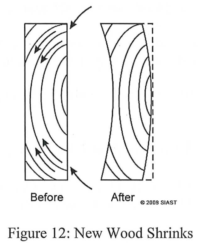
As discussed in the Block A module, wood is subject to warping when exposed to changing moisture conditions. Plain-sawn lumber from which wide members are often cut produce face grain which is especially susceptible to cupping (see figure 12 below).
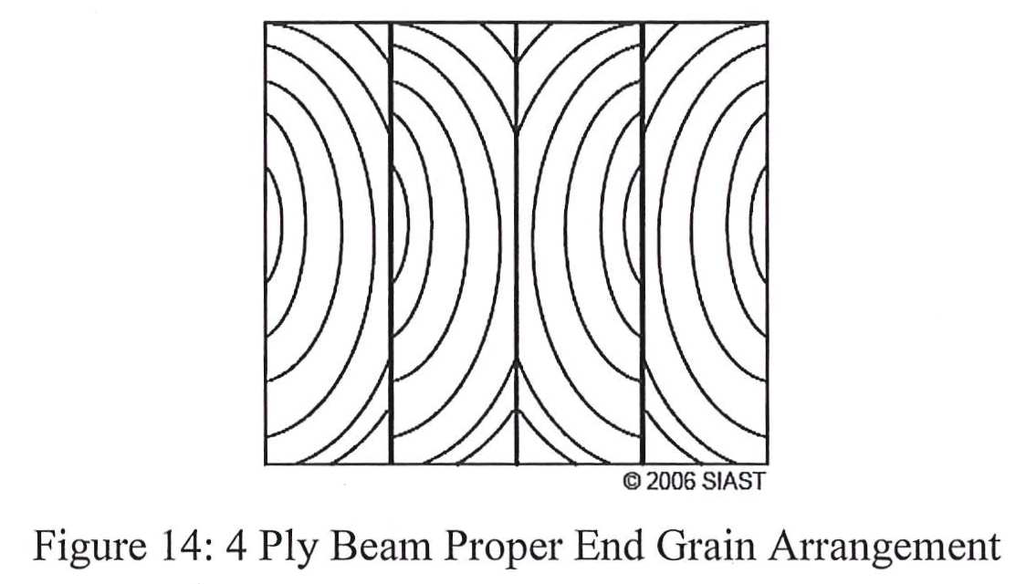
In order to counteract this, the boards must be oriented properly with the side susceptible to cupping oriented inwards (see figure 13). As with most framing applications, the crown of the board must also be oriented upwards.
Beam Supports
Beams are supported by either steel, concrete, or wooden columns. The spacing of the supports is dependent on the size of the beam and the load supported. Typically, an ideal spacing of supports is between 8”-0” and 10’-0”.
Wooden columns are typically required to be a minimum of 140 mm x 140 mm, or 184 mm in diameter in round columns but must not be smaller than the member they support. They can be solid lumber or laminated dimensional lumber. When using wooden columns on a concrete floor, they must be separated by a damp-proofing material (see 9.17.4.3 in the NBC).
Steel columns are much more popular as they are quick to install and are adjustable for installation and shifting foundations. As with wooden columns, the plate that supports the beam must be at least as wide as the beam.
Concrete columns are not as common in residential applications, but can be round, rectangular, precast, or cast in place.
Review Questions
- Name and describe the two methods of joining joists to foundation walls.
- True or False:
- The box-sill method allows for earlier pouring of concrete than joist-embedded method.
- The concrete holds down the joists when using the box-sill method.
- It is easier to level and align the floor using the joint-embedded method.
- Why is an extra joist required at the ends of a joist-embedded floor system?
- What is the minimum size allowed for a sill plate?
- According to the NBC, how is a sill plate levelled and anchored?
- What precaution must be taken when placing anchor bolts in a foundation wall?
- Use the following information to calculate the questions below:
- 26’-0” x 40’-0” Bungalow
- Hem-Fir No.2 Material
- 3 posts, equally spaced
- 8” foundation wall
- 4” end bearing of beam
- Spacing of posts
- Quarter point locations
- Supported length
- Size of beam required
- Max span of beam
- Fill in the following table:
|
Species |
Grade |
Size of House |
# of Storeys |
# of Posts |
Post Spacing* |
Supported Joist Length |
Beam Size |
|
D. Fir |
#1 |
6.7 m x 12.1 m |
1 |
3 |
|
|
|
|
Hem-Fir |
#2 |
8.5 m x 12.8 m |
2 |
4 |
|
|
|
|
Spruce |
#2 |
7.9 m x 13.4 m |
2 |
4 |
|
|
|
|
Hem-Fir |
#2 |
7.6 m x 12.8 m |
1 |
5 |
|
|
|
|
Spruce |
#2 |
8.5 m x 10.9 m |
1 |
2 |
|
|
|
|
D. Fir |
#1 |
6.7 m x 10.3 m |
2 |
3 |
|
|
|
*Foundation is 200 mm thick for all
- Fill in the following table:
|
|
House #1 |
House #2 |
|
Building size Species and grade of material Foundation wall Number of storeys Number of posts |
8.5 m x 12.8 m D.F #2 200 mm thick Two Four |
7.9 m x 12.2 m SPF #1 200 mm thick One Four |
|
a) Supported length
|
|
|
|
b) Clear overall span
|
|
|
|
c) Spacing of posts
|
|
|
|
d) Size of built-up
|
|
|
|
e) Maximum span for beam
|
|
|
|
f) End bearing of beam
|
|
|
|
g) Cut length of beam
|
|
|
- How much air space is required around the end of a wood beam which rests in a concrete wall? What is the purpose of this air space?
- What size beam pocket is required for a 4 ply 38 x 235 beam supporting a bungalow with a 2×6 sill plate and minimum end bearing?
- Wood column must be at least as wide as:
- Steel end bearing plates on steel columns must be at least ____ x ____ and at least ____ thick.
Topic 2 – Construct Conventional Floor Systems
Floor Joists
Floor joists are the members which span the floor system, either the entire foundation, or from the foundation to the beam or girder. They carry the live and dead loads of the internal structure (not including the exterior walls or roof system). Floor joists come in a number of varieties:
Wood Joists
Wood joists are the simplest method of framing a floor system. While 2×6 can be used in some circumstances, 2×8 or greater is much more common. The size chosen is dependent on a number of factors including load, span, spacing, species, grade, and type of joint restraint used. Joists can be spaced 12”, 16”, or 24” O.C., with 16” being the most common. The joists are fastened together with a header joist similar to a wall plate.
Partition Support and Openings
When a partition runs parallel to the joists, it must be supported by one of two methods:
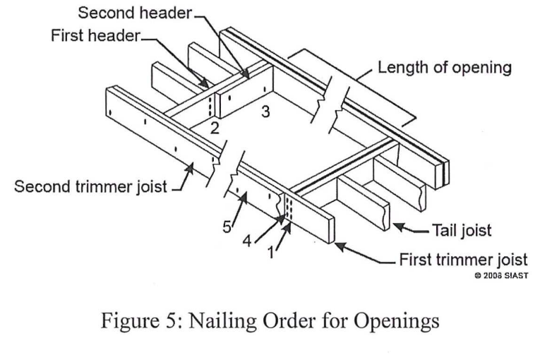 Openings in the floor such as a stairwell require special framing considerations. The joists that form the opening (trimmer joists) are doubled in openings greater than 800 mm wide. The header joists are also doubled in openings greater than 1200 mm wide. All pieces in openings are end nailed, and a specific nailing order must be adhered to. Figure 5 (right) shows the proper nailing order for floor openings.
Determining Required Joists
The dimensions required for floor joists is determined by the clear span, live load, joist spacing, species, grade, and type of joist restraint. For floor joists, the clear span is measured from inside edge of support (sill plate) to inside edge of support (beam) and is calculated by subtracting the width of the sill plate and half the thickness of the beam from half the building width, as shown below in figure 6:
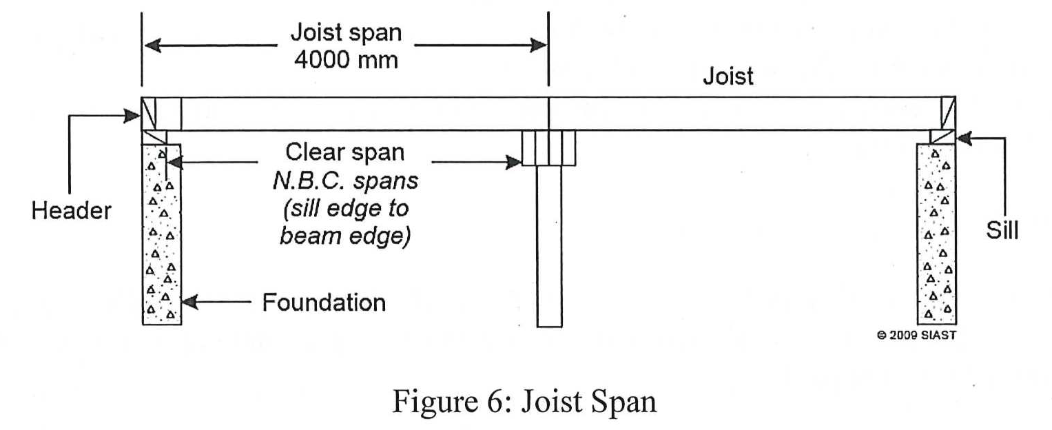
In the above figure, lets assume we have a 38×89 sill plate and a 4 ply 2×10 built-up beam (half the thickness = 38 mm x 2 = 76 mm). The clear span of the joists would be equal to 4000 mm – (89 + 76) = 4000 mm – 165 mm = 3835 mm or 3.835 m.
We will use the following building as an example to find the required joists:
The first step is to calculate the clear span of the joists. The joist span is equal to half the building width (9500 ÷ 2 = 4750 mm). The clear span of the joists is therefore equal to 4750 mm – (140 mm + ½ the beam thickness) = 4750 mm – (140 mm + 76 mm) = 4750 mm – 216 mm = 4534 mm or 4.534 m.
We will then use span table 9.23.4.3-A (General Cases) to find the joist dimension required. First find the 400 mm spacing column underneath “With Bridging”. We will then go down this column until we find the intersecting region that is applicable to Hem-Fir #2 (5 values are in this region with 1.90 being the first and 4.94 being the last). The value that is closest to 4.534 m without going under is 4.94. We will go to the left to find that we require 38 x 286 floor joists in this case.
When finding joists requirements, ensure you are using the correct table (usually general cases) and double check that the clear span was correctly calculated. Watch for the different types of joist restraint double check that the correct spacing is used.
Determining Joist Length
To calculate the joist length, deductions are taken from the joist span (1/2 the building width):
- NOTE: if the joists are lapped at the beam, no deductions are taken from the joist span
Using the example building from the previous page, we can find the cut length of the floor joists:
Floor Joist Quantity Takeoff
When calculating floor joist quantities, the following steps are followed:
- Divide building length by joist spacing (this calculates the number of spaces) and add 1 to start
- Multiply the product from the above step by 2 to account for both sides of the beam
- To the above result, some additions are made:
- Add 2 for each stairwell
- Add 1 for each partition running parallel to joists (for blocking or doubling of joist)
- Add 4 joists if joist embedded floor system
- For calculating the length of header material:
- Multiply the building length by 2 and add 5%
*** Use the following building to find the number of joists and header material required:
- 9200 x 11500 bungalow
- 600 mm spacing
- 1 stairwell
- 2 partitions running parallel to joists
- Joist embedded floor system
Special Considerations for Floor Joists
Notching and drilling of floor joists is allowed, but the regulations laid out in 9.23.5.1 in the NBC must be followed. Holes may not be greater than ¼ of the depth of the joist and notches must be from the top edge, a maximum of 1/3 of the joist depth, and within a distance equal to half the joist depth from a support. If the notch falls outside of the support, the depth of the joist must be increased by the depth of the notch.
Floor systems may also project beyond their supports to form cantilevered sections. Special consideration needs to be made for insulation and vapour barrier in these cases. Structural details can be found in section 9.23.9.9.
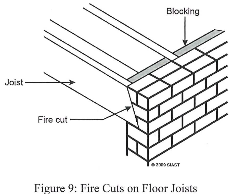 When framed into a masonry, a special angled cut called a fire cut is made and embedded into the masonry. In the event of a fire, the fire cut allows the floor system to fall in without putting strain on the masonry wall. If the joists were cut square and embedded, the failing of the floor system would pull on and cause a collapse of the masonry wall (see figure 9 right).
Joist Restraint
When joists span over a certain distance (2100 mm) joist restraint must be provided. This helps to stiffen the floor and to prevent the joists from twisting. Joist restraint (or intermediate support) can be provided by two means:
Laying Out Cross-Bridging
Layout of cross-bridging is accomplished using a framing square. The measurements used are determined by the joist depth (marked on the tongue) and the joist spacing (marked on the body). Normally, when marking stock on the framing square, we ensure that the same side of the square is used, and the same edge of the stock is marked. While the same side of the square must be used, we need to use opposing edges when marking cross bridging, as shown in the figure below.
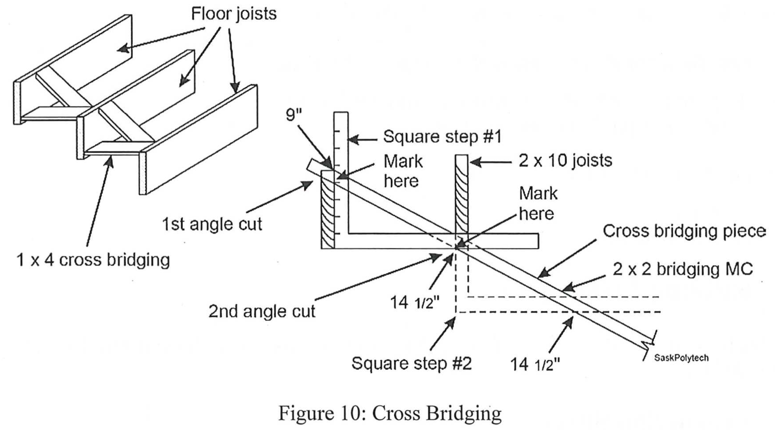
Another consideration we must make is adjustments to our measurements. To compensate for expansion, we will take off ¼” from the joist depth. In the case of figure 10 above, with 2×10 joists @ 16” O.C., the measurements used are 9” (9 ¼” – ¼”) and 14 ½” (16” – 1 ½”). The material will be marked as follows:
Joist Restraint Quantity Takeoff
Of the three methods of providing joist restraint, the two methods of strapping and blocking are the same. We will take the building length and multiply it by the number of rows of joist restraint and then add 5% (round up to nearest foot/meter):
- Length of material = (18m x 2) + 5% = 36m + 5% = 37.8 m/38 m
- Length of blocking = (42’ x 2) + 5% = 84’ + 5% = 88.2’/ 89’
For cross-bridging, the formula used accounts for both the doubling of material at each row, and the extra length required due to the cross-bridging being installed at an angle:
- Length of material = (48’ x 3) x 2 = 144’ x 3 = 432’
Review Questions
- Explain the difference between total span and clear span of a floor joist.
- What nailing is required at floor joist and sill plate connections?
- What two methods are acceptable when nailing joists to the side of the beam and why would these methods be used?
- What is the minimum bearing required for floor joists?
- When must a trimmer joist be doubled? When must a header joist be doubled?
- True or False:
- Tail joists are spiked to the single header joist before the double header joists are nailed on.
- A floor joist may be notched provided the notch is located at the bottom of the joist and in the proper location.
- The type of joist restraint used does not affect the size of floor joist required.
- Loading must be considered when choosing the size of floor joist required.
- Use the following information to answer the questions for both buildings below:
|
Information |
||
|
|
Building A |
Building B |
|
Material |
SPF Select |
Hem. Fir #2 |
|
Building size |
9.2 m x 14 m |
8.5 m x 12.1 m |
|
Beam |
Centered |
300 mm off center |
|
Joist spacing |
300 mm O.C. |
400 mm O.C. |
|
Sill |
38 x 184 |
N/A |
|
Posts |
4 – centered inside foundation walls |
3 – centered inside foundation walls |
|
Foundation |
250 mm |
200 mm beam filled |
|
Partitions |
4 |
3 on the wide span side of beam |
|
Openings |
None |
1 on the narrow span side of beam |
|
Live load |
1.9 kN/m2 (general cases, 9.23.4.2 – A) |
1.9 kN/m² (general cases, 9.23.4.2 – A) |
|
Joist restraint |
Cross-bridging |
Strapping only |
- Calculate the number of joists required
- Minimum dimension of floor joists
- Cut length of floor joists
- Length of floor joists to order
- Linear measurement of sill (Building A only)
- What is the maximum amount 38 x 184 floor joists can be cantilevered if they support a roof load? What if they are 38 x 235?
- Using the following image, answer the questions below:
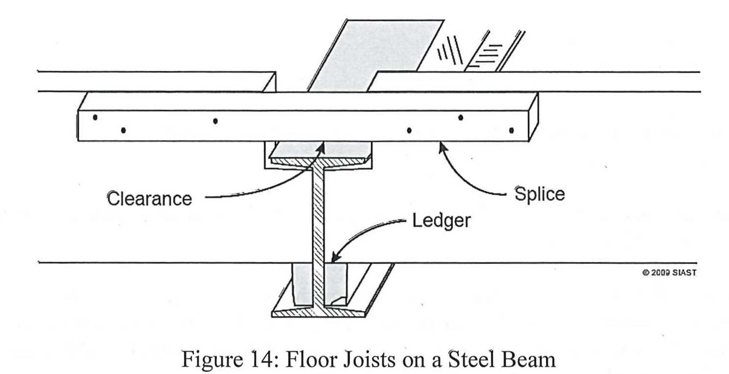
- The size and length of the splice must be _____.
- The space between the splice and the steel beam should be at least _____.
- What is the purpose of the clearance space?
- The clearance between a masonry fireplace chimney and floor framing shall not be less than _____ mm for interior chimneys, and _____ mm for exterior chimneys.
- Why should solid bridging be applied before floor sheathing? Why are the bottoms left un-nailed until after sheathing and partitions are installed?
- True or False:
- locking tightly fitted between joists and securely nailed is acceptable for restraining joist twisting.
- Gypsum board attached directly to joist can be considered equivalent to strapping.
- If the ceiling is furred or clad with plywood, no additional restraint is required between supports.
