Study Tips: Create a Summary from Text
When you identify a topic that you are not familiar with, it is important to take note of that topic for later study. Remember:
- Your goal is to study only what you don’t know. There is so much material, don’t waste your time on reading things you already know.
- You need to review outside the class. The time spent in the classroom is not enough to enable you to pass. Spend time in the classroom figuring out what you don’t know. Spend time at home each night going over your glossary and creating summaries.
- When you study at home, don’t study what was just learned that day. Review all your glossary items and summaries from the start of the class to the current day. While this sounds like a lot of work, you will find that after reviewing your notes from the beginning several times, you will practically have them memorized and it won’t take long.
When you read through a section of text there will be a lot of extra “fluff” that you already know, or just is there to make the text more readable. Your job is to cut out all the “fluff” and information you already know. This can be done by taking notes.
Exercise
Part of the reading required for “Instruction Sheet 7.01.4 – Perform Basic Transit Functions” is contained in the Andres and Smith textbook: “Principles and Practices of Commercial Construction”. Read the following excerpt from this text and be prepared to take notes.
Step 1:
- If there are questions at the end of the chapter, read them first. This may help you pick out important pieces of information as you are reading the text.
Step 2:
- Read the whole text over uninterrupted. You can skim to get the general idea. It is also sometimes a good idea to create an outline on your note paper by using the headings in the text, with a little space to fill in later. (If you are using the Cornell Method, you would write this on the right side of the page.)
Step 3:
- Reread the text paragraph by paragraph. At this point, write and/or highlight the key points after reading the paragraph.
Step 4:
- Go back and summarize. If using the Cornell Method, write a summary at the bottom of the page. Go back to the questions at the end of the chapter, if there are any, and try answer them. Write the answers down.
Chapter 2 Site Layout
[Diagrams have been omitted]
Once the building site has been established, it is necessary to locate the building precisely within the boundaries of the site and to indicate to what depth excavation must be performed. When the site is not level, excavation depths will vary, and these variations must be shown. Included among the drawings for a building is the site plan (see Figures 2-1(a) and (b)), which shows the property lines, available utilities, location of trees, and the like, and the location of the building. Approaches and slopes of finished grades are usually shown. In addition, a benchmark or datum point is often indicated on the plan. A benchmark is a point of known elevation, established by registered survey and marked by a brass plate on a post at or near ground level or by a brass plug set into a building, bridge, or other permanent structure, near ground level. A datum point is a reference point, usually given an arbitrary elevation, for example, 100 ft or 0.0 ft (100.00 m or 0.0 m) such as a manhole cover or some permanent surface at or near ground level on an adjacent building or other structure.
SURVEYING INSTRUMENTS
Surveying instruments are used to run building control lines, lay out angles, and determine the various differences in elevation required during the construction of a building and its foundations. These precision instruments incorporate a telescope, leveling devices, horizontal and vertical cross hairs, and finely calibrated scales for measuring horizontal and vertical angles. Three basic types of surveying instruments are available for use in the construction industry: the level, also known as a builders’ level; the level transit; and the theodolite or transit. Each type of instrument is available in a wide variety, from basic mechanical models to sophisticated electronic ones. Electronic models with software packages that contain various surveying programs, data storage capabilities, and remote entry infrared keyboards are available. These are known as total station surveying instruments. These instruments have the hardware to transmit field data from the building site directly to the office, thus saving time and decreasing the chance of errors occurring when the field data are transcribed to the building plans. Surveying instruments equipped in this fashion are used to their best advantage in topographic surveys and the accurate positioning of structures. In spite of all this sophistication, the use and operation of all surveying instruments require the understanding of basic surveying principles.
The Level
Two varieties of levels are shown in Figures 2-2 and 2-3. The level operates in a horizontal plane only, and its use is limited to operations that can be done in that plane, such as measuring horizontal angles and differences in elevation. All levels have the same basic parts: a leveling mechanism, a level vial with bubble, a telescope with an objective lens, an eyepiece and focusing knob, a horizontal circle with vernier scale, a mechanism for fine adjustments of horizontal movement, and cross-hair focusing. Figure 2-2 provides a good illustration of the various components of a level; newer models have been streamlined and reduced in size and weight.
Automatic Level
Figure 2-4 shows an automatic level. This type of level has a self-leveling feature, which makes its setup much faster and ensures that the instrument remains `level during use. Stadia marks on the cross hairs allow the instrument user to establish horizontal distances when sighting on a special rod known as a stadia rod. Although relatively durable, this type of level must be used with care to avoid damaging the self-leveling mechanism
Electronic Levels
The latest generation of survey level is the electronic variety, which incorporates the latest in microchip technology. This instrument is both self-leveling and self-reading. All the operator must do is sight on the rod and press a button; in approximately 4 sec, the electronic equipment on the level does the rest (Figure 2-5). The electronic circuitry provides superb accuracy and ease of use, thereby reducing the chance for error. The rod reading and horizontal distance are displayed on a small screen (Figure 2-5) in either metric or standard units. Elevations are calculated, and readings can be stored automatically in the data storage unit. Power is provided by a rechargeable internal battery usually good for a full day of work. Because of its speed, accuracy, and data storage capabilities, the electronic level is excellent for topographical surveys, positioning of pipelines, monitoring of structural deformations, and highway construction applications.
Laser Level
The laser level (Figure 2-6) is a direct development of space-age technology. The construction laser is a low-energy laser and should not be confused with the high-energy lasers used for other purposes. Al- though the laser is completely safe to use, looking into the laser beam itself should be avoided as damage to the eye could result in an effect like looking directly into the sun or any other bright light. The laser level produces a controlled beam of red light 3/16 in. to 3/8 in. (5 to 10 mm) in diameter by exciting the electrons in a helium-neon gas with electrical energy. The beam can be made to rotate about the instrument, producing a plane of light. If the instrument is level, the plane of light can be used as a reference plane for leveling. When an object such as a survey rod intersects the plane of light, the laser becomes visible as a red line. The person holding the rod can then take a reading, without the need for another person at the instrument. Because the laser is a beam of light that can be aimed in a particular direction, it provides a perfect reference line for use in construction applications that require strict alignment. Typical applications are horizontal leveling, vertical alignment, and grade control for laying of pipe.
Horizontal Leveling
Once the instrument is leveled and the laser beam rotated, the resulting plane of light created by the laser can be used as a reference for aligning screeds for concrete floors (Figure 2-7), pouring concrete slabs, and installing suspended ceilings (Figure 2-8).
Vertical Alignment
The instrument head can be rotated 90° so that the resulting plane is now vertical. The plane of light can then be used for the alignment of formwork, as for high-rise construction In some applications, the laser is set inside the building to monitor the vertical alignment of the structure as each new floor is added (Figure 2-9).
Grade Alignment
Another popular use for the laser is in aligning pipes at specific grades to ensure proper drainage. The laser beam is preset at a specific grade and then set in the trench at one end of the pipeline. Pipe sections are then laid by lining up the center of the pipe, with the aid of a target, on the laser beam (Figure 2-10). When the pipe is of a large diameter, an alternative approach is to place the preset laser level on top of the pipe and align the top of the pipe with respect to the laser beam. Levels can be taken using a normal surveying rod or with the use of a special rod that has a traveling laser-sensitive target (Figure 2-11). The target moves up and down the rod until it intersects the rotating beam of light. Once the plane of light strikes the target, the target locks on the light beam, allowing an accurate rod reading to be taken.
Andres, C. K., & Smith, R. C. (2009). Chapter 2 Site Layout. In Principles and practices of commercial construction (pp. 21–27). Pearson Prentice Hall. Reproduced under fair use.
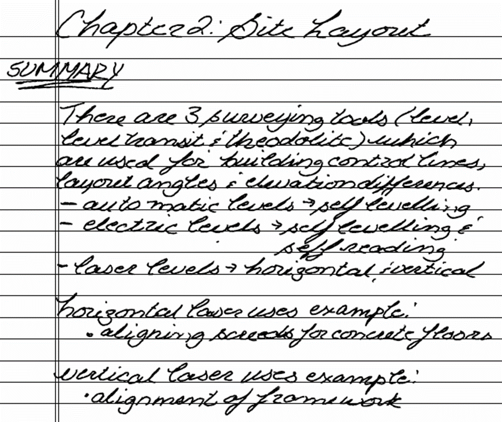
Sample Notes


