Topic 1 – Types of Views, Lines, and Symbols
Architects can use several types of views to depict a building, each of which has a unique purpose and set of information.
A pictoral view is drawn with perspective, meaning lines converge on the vanishing point. The drawback of this drawing is that lines get smaller the further away they are from the viewer to create a perception of distance. Pictoral views and presentations drawings can be artistic in nature and are used more for marketing purposes
Multiview drawings are useful for building because they contain measurements and other physical information. There are three types: plan, elevation, section, and details.
A plan view is further subdivided into types:
Plot plan
Foundation plan
Floor plan
Framing plan
Elevation drawings show the shape and size of exterior vertical finishings. These also can be used to describe kitchen and bathroom cabinet layouts.
Section view details part of another view. The section reference line indicates what part of the view is being detailed
Details views are used for intricate or complicated construction. They are drawn at a larger scale to clearly depict every dimension or detail.
A schedule is an attached document which gives detailed information about some repetitive aspects of a plan. For example, a particular door and frame in a commercial building may be used one hundred times. Rather than detailing the door on the plan each time, the door is referenced to a schedule. The details for that particular application are listed once in the schedule.
For details and drawings, refer to the textbook, Carpentry
“Architectural Plans”
“Types of Views”
“Schedules”
Types of Views
They way objects are drawn on a print follow three particular views.
They are:
Oblique
Isometric
Orthographic
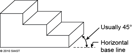
Oblique- this drawing has the front of the object drawn along a horizontal base line square to the page. Usually, the largest side showing the most detail is selected for the front view. The side is drawn receding back at an angle of 45 degrees
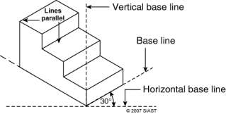
Isometric – An isometric drawing has three base lines, one vertical at 90° to the horizontal, and two at 30° to the horizontal. Contours of the object recede to the left and to the right
Perspective – Perspective drawings are the most realistic to look at, but the hardest to draw. The angled lines in the drawing are not parallel they meet at a vanishing point if extended far enough. Some drawings may have only one vanishing point, while others may have two vanishing points

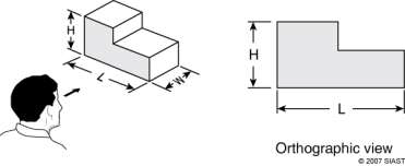
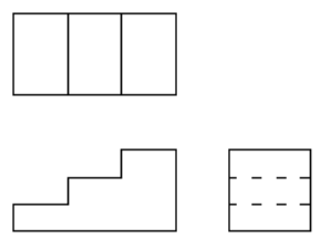
Orthographic projection – An orthographic drawing is a two-dimensional view showing a side of an object viewed directly at 90°. Orthographic drawings are flat views so they don’t show any depth. When viewing a drawing of a house each elevation is shown in a separate orthographic view.
Types of Lines
Scales
Scales are proportional representations between the blueprint and the actual construction. Throughout a set of blueprints different scales will be used. Smaller features are drawn at a larger scale to provide a clearer view. These are referred to as Details.
Lines used on blueprints will vary in thickness or design to represent different information.
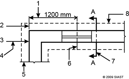
Dimension line – indicates the distance that they are dimensioning by the measurement next to them.
Extension line – used to show the extent of a dimension and are located between the object and the dimension line. Extension lines don’t quite touch the object and are drawn lighter than object lines.
Object line – broad solid lines used to indicate the visible portion of an object in this view.
Leader – arrows that point to an object from a notation on the print.
Break line – used where part of the drawing is omitted or cut off that in reality would continue. Its purpose is to save space for other information on the print.
Centre line – used to locate the centre of an object typically a window, door or partition wall.
Cutting plane line – show where a section view is taken from and uses arrows to show which direction you are looking at in the section view.
Hidden line – used to show important objects that would otherwise not be visible in that view. Common examples include cabinets on a floor plan or footings on a foundation plan.
Symbols
Symbols are used on construction drawings to represent the building materials, objects and convey information. Some materials are represented by one symbol when shown in a plan view such as a floor plan; but the same material shown in a section view is represented by a different symbol. Not all architects/draft persons will use the same symbols. Often a legend is part of the blueprint indicating what each symbol represents.
Abbreviations
Abbreviations are used on construction documents to save space.
For further information please review the following:
From the textbook, Carpentry, study the following sections:
“Types of Lines”
“Dimensions”
“Abbreviations”
“Symbols in Architectural Plans and Building Codes”
For more details, review Instruction sheets on Brightspace.
BPRT 100 Learning Outcome 1 Learning Step 1,2,3 and 4 (Page 5-16)
IS 4.2 Symbols
BPRT 200 Learning Outcome 1 Learning Step 1 (Page 8-15)
IS 1.2 Symbols
Review in text:
Understanding Construction Drawings, Chapter 4
Review Questions
List and describe the three types of pictorial drawings
Match the following statements to the corresponding letter:
Plot Plan
Foundation plan
Floor Plan
Framing plan
Elevations
Section Views
Details
Schedules
___ Shows a horizontal cut through 4-5 feet above the floor
___ Shows a horizontal cut through the foundation walls
___ Shows support beams and girders
___ Shows information about the lot
___ Shows a skeleton view
___ Shows shapes and finishes of all sides of the exterior of a building
___ Shows small parts drawn at a large scale
___ Used to conserve space on floor plans
___ Shows direction of sloping ground
___ Shows locations of windows and doors
___ Shows direction of footings
___ Shows size, direction, and spacing of framing members
___ Uses symbols with letters or numbers to refer you to the appropriate page
___ Gives detailed information about sizes and types of windows or doors to be installed
Floor plans are generally drawn at a scale of _____ (indicate for both metric and imperial).
Exterior door symbols are drawn with a line representing the outside edge of the _____.
How are ceiling beams represented on floor plans?
Exterior dimensions on a wood frame building are taken from the outside face of the _____.
In wood frame construction, doors and windows are dimensioned to their _____.
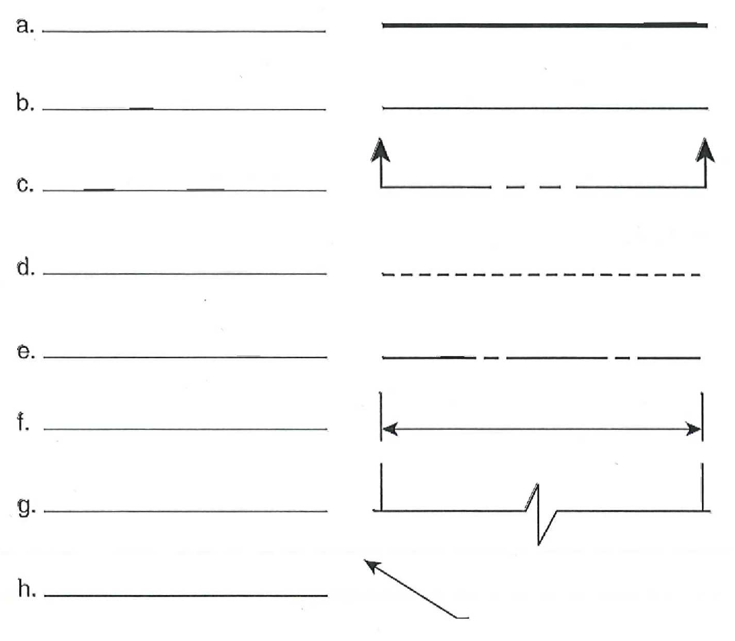
Name the following lines
Note: Additional review questions can be found in BPRT 100 Review Exercise 1.2, Review Exercise 2.2, Review Exercise 3.2 and Review Exercise 4.3
