17
In this chapter we consider a more abstract approach to heat engine, refrigerator and heat pump cycles, in an attempt to determine if they are feasible, and to obtain the limiting maximum performance available for these cycles. The concept of mechanical and thermal reversibility is central to the analysis, leading to the ideal Carnot cycles. (Refer to Wikipedia: Sadi Carnot a French physicist, mathematician and engineer who gave the first successful account of heat engines, the Carnot cycle, and laid the foundations of the second law of thermodynamics).
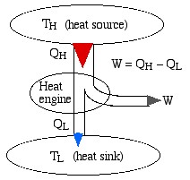
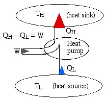
We represent a heat engine and a heat pump cycle in a minimalist abstract format as in the following diagrams. In both cases there are two temperature reservoirs TH and TL, with TH > TL.
![]()
![]()
![]()
![]()
![]()
![]()
In the case of a heat engine heat QH is extracted from the high temperature source TH, part of that heat is converted to work W done on the surroundings, and the rest is rejected to the low temperature sink TL. The opposite occurs for a heat pump, in which work W is done on the system in order to extract heat QL from the low temperature source TL and “pump” it to the high temperature sink TH. Notice that the thickness of the line represents the amount of heat or work energy transferred.
We now present two statements of the Second Law of Thermodynamics, the first regarding a heat engine, and the second regarding a heat pump. Neither of these statements can be proved, however have never been observed to be violated.
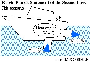
The Kelvin-Planck Statement: It is impossible to construct a device which operates on a cycle and produces no other effect than the transfer of heat from a single body in order to produce work.
We prefer a less formal description of this statement in terms of a boat extracting heat from the ocean in order to produce its required propulsion work:
Heat Engine
![]()
![]()
![]()
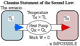
The Clausius Statement: It is impossible to construct a device which operates on a cycle and produces no other effect than the transfer of heat from a cooler body to a hotter body.
![]()
![]()
Temperature
![]()
Heat Pump
![]()
![]()
Equivalence of the Clausius and Kelvin-Planck Statements
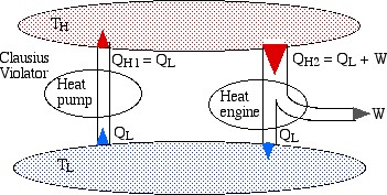
It is remarkable that the two above statements of the Second Law are in fact equivalent. In order to demonstrate their equivalence consider the following diagram. On the left we see a heat pump which violates the Clausius statement by pumping heat QL from the low temperature reservoir to the high temperature reservoir without any work input. On the right we see a heat engine rejecting heat QL to the low temperature reservoir.
![]()
![]()
![]()
![]()
![]()
![]()
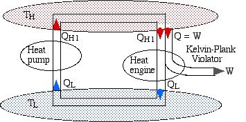
If we now connect the two devices as shown below such that the heat rejected by the heat engine QL is simply pumped back to the high temperature reservoir then there will be no need for a low temperature reservoir, resulting in a heat engine which violates the Kelvin-Planck statement by extracting heat from a single heat source and converting it directly into work.
![]()
![]()
![]()
![]()
![]()
![]()
Mechanical and Thermal Reversibility
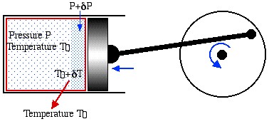
Notice that the statements on the Second Law are negative statements in that they only describe what is impossible to achieve. In order to determine the maximum performance available from a heat engine or a heat pump we need to introduce the concept of Reversibility, including both mechanical and thermal reversibility. We will attempt to clarify these concepts in terms of the following example of a reversible piston cylinder device in thermal equilibrium with the surroundings at temperature T0, and undergoing a cyclic compression/expansion process.
![]()
![]()
![]()
![]()
For mechanical reversibility we assume that the process is frictionless, however we also require that the process is a quasi-equilibrium one. In the diagram we notice that during compression the gas particles closest to the piston will be at a higher pressure than those farther away, thus the piston will be doing more compression work than it would do if we had waited for equilibrium conditions to occur after each incremental step. Similarly, thermal reversibility requires that all heat transfer is isothermal. Thus if there is an incremental rise in temperature due to compression then we need to wait until thermal equilibrium is established. During expansion the incremental fall in temperature will result in heat being transferred from the surroundings to the system until equilibrium is established.
In summary, there are three conditions required for reversible operation:
- All mechanical processes are frictionless.
- At each incremental step in the process thermal and pressure equilibrium conditions are established.
- All heat transfer processes are isothermal.
Carnot’s Theorem
Carnot’s theorem, also known as Carnot’s rule, or the Carnot principle, can be stated as follows:
No heat engine operating between two heat reservoirs can be more efficient than a reversible heat engine operating between the same two reservoirs.
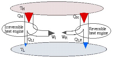
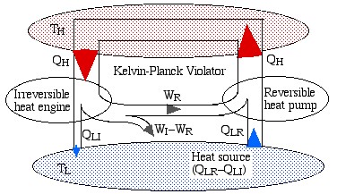
The simplest way to prove this theorem is to consider the scenario shown below, in which we have an irreversible engine as well as a reversible engine operating between the reservoirs TH and TLH from the high temperature reservoir, however the irreversible engine produces more work WI than that of the reversible engine WR.
![]()
![]()
![]()
![]()
![]()
![]()
Note that the reversible engine by its nature can operate in reverse, i.e. if we use some of the work output (WR) from the irreversible engine in order to drive the reversible engine then it will operate as a heat pump, transferring heat QH to the high temperature reservoir, as shown in the following diagram:
![]()
![]()
![]()
![]()
![]()
![]()
![]()
![]()
Notice that the high temperature reservoir becomes redundant, and we end up drawing a net amount of heat (QLR – QLI) from the low temperature reservoir in order to produce a net amount of work (WI – WR) – a Kelvin-Planck violator – thus proving Carnot’s Theorem.
Corollary 1 of Carnot’s Theorem:
The first Corollary of Carnot’s theorem can be stated as follows:
All reversible heat engines operating between the same two heat reservoirs must have the same efficiency.
Thus regardless of the type of heat engine, the working fluid, or any other factor if the heat engine is reversible, then it must have the same maximum efficiency. If this is not the case then we can drive the reversible engine with the lower efficiency as a heat pump and produce a Kelvin-Planck violator as above.
Corollary 2 of Carnot’s Theorem:
The second Corollary of Carnot’s theorem can be stated as follows:
The efficiency of a reversible heat engine is a function only of the respective temperatures of the hot and cold reservoirs. It can be evaluated by replacing the ratio of heat transfers QL and QH by the ratio of temperatures TL and TH of the respective heat reservoirs.
Thus using this corollary we can evaluate the thermal efficiency of a reversible heat engine as follows:
![Rendered by QuickLaTeX.com COP_\text{HP}= \dfrac{Q_\text{H}}{W} = \dfrac{Q_\text{H}}{Q_\text{H}-Q_\text{L}}= \dfrac{1}{1-\dfrac{Q_\text{L}}{Q_\text{H}}} \xRightarrow[\dfrac{Q_\text{L}}{Q_\text{H}}=\dfrac{T_\text{L}}{T_\text{H}}]{+ \ +}COP_\text{HP, rev} = \dfrac{1}{1-\dfrac{T_\text{L}}{T_\text{H}}}](https://pressbooks.pub/app/uploads/quicklatex/quicklatex.com-29c4530c8469b3076841ada1c7bf6bbe_l3.png)
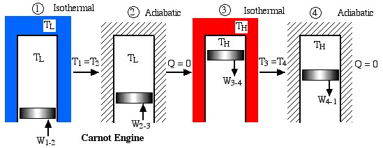
Notice that we always go into “meditation mode” before replacing the ratio of heats with the ratio of absolute temperatures, which is only valid for reversible machines. The simplest conceptual example of a reversible heat engine is the Carnot cycle engine, as described in the following diagram:
![]()
![]()
![]()
![]()
![]()
![]()
![]()
![]()
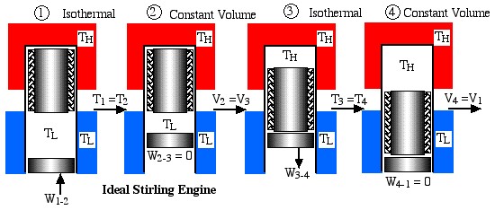
Obviously a totally impractical engine which cannot be realized in practice, since for each of the four processes in the cycle the surrounding environment needs to be changed from isothermal to adiabatic. A more practical example is the ideal Stirling cycle engine as described in the following diagram:
![]()
![]()
![]()
![]()
![]()
![]()
![]()
![]()
![]()
![]()
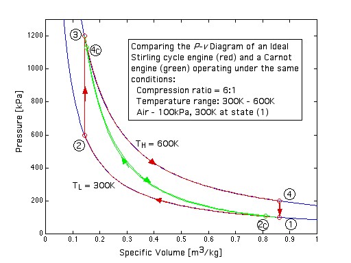
This engine has a piston for compression and expansion work as well as a displacer in order to shuttle the working gas between the hot and cold spaces, and was described previously in Chapter 3. Note that under the same conditions of temperatures and compression ratio the ideal Carnot engine has the same efficiency however a significantly lower net work output per cycle than the Ideal Stirling cycle engine, as can be easily seen in the following diagram:
![]()
![]()
![]()
![]()
When the reversible engine is operated in reverse it becomes a heat pump or a refrigerator. The coefficient of Performance of these machines is developed as follows:
![Rendered by QuickLaTeX.com COP_\text{HP}= \dfrac{Q_\text{H}}{W} = \dfrac{Q_\text{H}}{Q_\text{H}-Q_\text{L}}= \dfrac{1}{1-\dfrac{Q_\text{L}}{Q_\text{H}}} \xRightarrow[\dfrac{Q_\text{L}}{Q_\text{H}}=\dfrac{T_\text{L}}{T_\text{H}}]{+ \ +}COP_\text{HP, rev} = \dfrac{1}{1-\dfrac{T_\text{L}}{T_\text{H}}}](https://pressbooks.pub/app/uploads/quicklatex/quicklatex.com-29c4530c8469b3076841ada1c7bf6bbe_l3.png)
![Rendered by QuickLaTeX.com COP_\text{R}= \dfrac{Q_\text{L}}{W} = \dfrac{Q_\text{L}}{Q_\text{H}-Q_\text{L}}= \dfrac{1}{\dfrac{Q_\text{H}}{Q_\text{L}}-1} \xRightarrow[\dfrac{Q_\text{H}}{Q_\text{L}}=\dfrac{T_\text{H}}{T_\text{L}}]{+ \ +}COP_\text{R, rev} = \dfrac{1}{\dfrac{T_\text{H}}{T_\text{L}}-1}](https://pressbooks.pub/app/uploads/quicklatex/quicklatex.com-5eb98f90f328841622d6a2432154e80a_l3.png)
Solved Problem
![]()
![]()
![]()
![]()
![]()
![]()
![]()
![]()
![]()
![]()
![]()
![]()
![]()
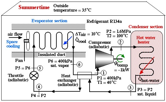
Under the conditions shown in the diagram the Coefficient of Performance of the hot water heater (COPHW) is 4.41, and that of the space cooling air conditioner (COPAC) is 3.41. Assuming that this system is required to maintain the home air at 20°C and the hot water at 50°C, we wish to determine the maximum possible theoretical Coefficients of Performance that could be obtained under these conditions.
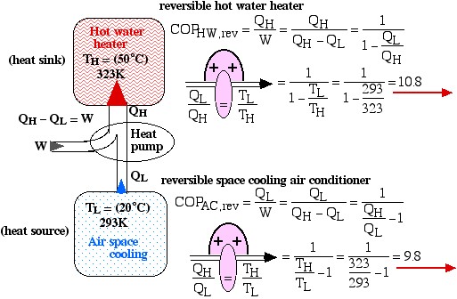
- Draw a diagram representing the heat pump system showing the flow of energy and source and sink temperatures and determine the following:
- The maximum possible Coefficient of Performance of a hot water heater (COPHW) that could be obtained by a reversible heat pump.
- The maximum possible Coefficient of Performance of a space cooling air conditioner (COPAC) that could be obtained by a reversible heat pump.
- Comparing the actual Coefficients of Performance shown above to those of the reversible heat pump determine if the actual heat pump shown above is feasible. State the reasons for your conclusion.
Derive all equations used starting from the basic definition of COPHW and COPAC and the Carnot relations for the ratio of heats of a heat pump.
Solution: For 1), 2), and 3) we need to reduce the system complexity shown above to an energy flow diagram showing only the basic requirements – cool the air to 20°C and heat the water to 50°C. Given the temperature if the heat source (20°C) and the heat sink (50°C) we can evaluate the respective reversible Coefficients of Performance.

![Rendered by QuickLaTeX.com \xRightarrow[\dfrac{Q_\text{L}}{Q_\text{H}}=\dfrac{T_\text{L}}{T_\text{H}}]{+ \ +} = \dfrac{1}{1-\dfrac{T_\text{L}}{T_\text{H}}}=\dfrac{1}{1-\dfrac{293}{323}}=10.8](https://pressbooks.pub/app/uploads/quicklatex/quicklatex.com-8d087fcca4c941fca1990717b05f8161_l3.png)

![Rendered by QuickLaTeX.com \xRightarrow[\dfrac{Q_\text{H}}{Q_\text{L}}=\dfrac{T_\text{H}}{T_\text{L}}]{+ \ +} = \dfrac{1}{\dfrac{T_\text{H}}{T_\text{L}}-1}=\dfrac{1}{\dfrac{323}{293}-1}=9.8](https://pressbooks.pub/app/uploads/quicklatex/quicklatex.com-f3d6f12ebdafaa5da7957cd2ed950345_l3.png)
![]()
![]()
![]()
![]()
![]()
![]()
![]()
![]()
For question 4) we use the accumulated knowledge that the conditions for thermal and mechanical reversibility are so difficult to realize that no practical heat pump or heat engine can attain more than 50% to 60% of the equivalent reversible (Carnot) performance. Thus comparing the actual to the reversible Coefficients of Performance we obtain:
![]()
![]()
