5
The California Memorial Stadium, like the Hearst Memorial Mining Building (see section 1), was designed by John Galen Howard. It is a tribute to UC Berkeley alumni who died in World War I. It is located at the base of the Berkeley Hills directly at the mouth of Strawberry Canyon. This spot on the easternmost part of the campus was chosen after a more convenient location in downtown Berkeley was rejected by local merchants. When construction of the sports arena commenced in December 1922 the University’s administration was fully aware that the future stadium would straddle the Hayward Fault.
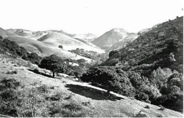
How did the landscape in this area look, before the first dirt was excavated? Strawberry Canyon was still largely undeveloped, except for a dairy farm where the Botanical Garden is located today. On Panoramic Hill to the south of the creek, Fredrick Law Olmsted, the landscape architect of Golden Gate Park and New York’s Central Park fame, had – at the University’s request – laid out a gracious residential neighborhood. At the base of the Berkeley Hills where Strawberry Creek encountered the Hayward Fault its straight downhill flow was blocked by a shutter ridge, transported there by the right lateral movement of the Hayward Fault. As a consequence, the creek turned sharply to the northwest for about 1100 ft, before it resumed its westward downhill flow. As with many other creeks on the west side of the East Bay Hills the bed of Strawberry Creek is an offset stream channel.
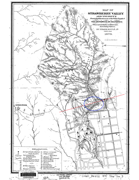
Howard managed to squeeze the large stadium with its more than 72,000 seats right into the depression caused by the erosion of Strawberry Creek where its bed bends to the northwest. This was exactly the spot for which Frank Soulé, who would later become the first dean of UC Berkeley’s College of Civil Engineering, had in 1875 proposed to dam Strawberry Creek into a reservoir to secure the drinking and irrigation water supply for the growing campus (see figure 5.2). The plan for the reservoir, however, never came to fruition.
To build the stadium Howard made use of the natural bowl shape. In addition he cut away a section of what is now Tightwad Hill at the base of the Berkeley Hills. It consists of sandstone from the Great Valley Sequence of the Cretaceous period. For their work the engineers used hydraulic mining techniques similar to those developed during the Californian Gold Rush. The newly created slope was turned into the foundation for the bleachers on the east side of the field. At the same time Strawberry Creek was diverted into a 4 ft diameter culvert. It initially runs under the stadium and then turns west (downhill) where the parking garage below Maxwell Family Field is today. After a total length of 1450 ft the culvert daylights near the Women’s Faculty Club (blue circle in figure 2). From there Strawberry Creek runs through campus as a lovely gurgling brook. Because the capacity of the culvert proved insufficient during the Christmas Floods of 1964, a larger bypass was constructed under Stadium Way.
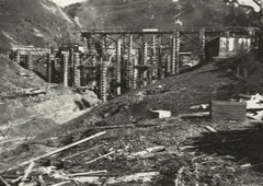
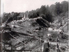
Fig. 5.3, left panel: A view from the northwest of the construction site in early 1923. The ditch seen in the lower left is the offset bed of Strawberry Creek, which also marks the fault line of the Hayward Fault. Right panel: opposite view to the northwest in an earlier phase of the construction. Horse drawn carriages were used to remove excess excavation material. The Campanile can be seen faintly in the upper left.
Because the approximate location of the Hayward Fault, its potential for significant earthquakes were known at the time of construction, Howard adapted the design of the stadium accordingly. He placed expansion joints in the stadium exterior walls mainly at the points where the wall intersected the fault. We will see examples at points 5.2 and 5.4 on this tour. Despite the enormous engineering challenges, the construction of the stadium was finished in only 11 months. The arena opened on November 24th, 1923, just in time for the Big Game against Stanford, which, by the way, the Bears won 9-0.
Over the next eight decades the Beaux Art façade of the exterior wall of the football arena became one of UC Berkeley’s iconic symbols. In 2006 the stadium was even placed as a landmark on the National Register of Historic Places (ref# 06001086). In the meantime the tectonic movement along the Hayward Fault tugged relentlessly on the structure – with dire consequences. Columns in the interior had bent and bulged, façades had cracked and during a seismic safety study the stadium received a rating of “poor”, which means that the building had become an “appreciable life hazard” during an earthquake. Hence in early 2010 the University’s Board of Regents approved the retrofit and the complete renovation of the stadium.
During this reconstruction, which cost an estimated $445 million, the stadium was entirely gutted. Only the exterior wall had to be left untouched because of the stadium’s status as a protected landmark (see figure 5.4). The bleachers and all athletic and spectator facilities were completely rebuilt according to the latest seismic mitigation techniques. The old press box was demolished and a new structure built in its place, independent of the rest of the stadium.
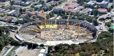
This areal view from the east is looking over the stadium towards campus. When this picture was taken the construction of the new press box had not yet commenced.
As of this writing not even five years have passed since the reopening of the stadium, but the Hayward Fault has already been tirelessly at work. At the following stops we will see some of the effects which the fault creep of a few millimeters per year has already had on the rebuilt stadium. Some signs are still rather subtle, but given the unstoppable movement of the tectonic plates under northern California, the small cracks and movements visible today will grow larger with each passing year.
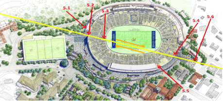
From the borehole continue the walkway uphill for a few steps until you reach a flight of concrete stairs. Walk down a few of these stairs, but not farther than the first platform. Stop there. This is our initial point of interest in the stadium.
5.1 Stairway on North Side of Stadium
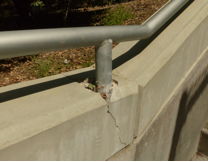
The stairway on which you are standing was built during the stadium’s renovation in 2012. If you walked the whole length of the stairway, you would not find any cracks in the concrete steps or in the wall holding the hand rail, except here on the first platform from the bottom. There are several subtle, cracks crossing the base of the platform. Much more noticeable, however, are the cracks where at least three handrail supports are set into the concrete wall (see figure 5.6). The reason for these cracks is not shoddy workmanship during construction. Instead the cracks are caused by the aseismic creep of the Hayward Fault, which crosses the stairway exactly at the platform on which you are standing.
Continue down the stairs. Go through the gate at the bottom of the stairway. Immediately turn left and walk to the exterior stadium wall on the left side of the north tunnel. Walk for a few yards in a clockwise (left) direction along the wall until you reach a corner. To the left is a joint between two sections of the wall, which is filled with sealant.
5.2 Exterior Wall – North Side of Stadium
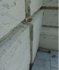
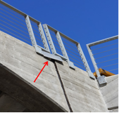
When Howard designed the stadium in the early 1920’s he was aware of the fault’s location. Hence he separated the exterior wall into several sections, which were supposed to move independently during an earthquake. Currently, you are standing at one of these separations – we will see another one at stop 5.4. Because no significant earthquake has happened along the Berkeley section of the Hayward Fault during the existence of the stadium, Howard’s concept was never tested. However here at the northern expansion joint, the two sections of the stadium’s exterior wall have slid by about 1.5 inches due to the aseismic creep along the fault (see figure 5.7). During the renovation, this expansion joint was filled with a flexible sealant. Note how the sealant is cracking as a result of the fault’s movement.
When you look back from your current location to the stairway and to the borehole (stop 4) you will notice that our last stops lie on a straight line facing northwest. This is the fault line.
Walk back to the tunnel entrance and enter it. Don’t walk all the way to the playing field but stop at the point where the tunnel daylights.
5.3 North Tunnel
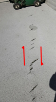
Where the tunnel daylights, the smooth concrete floor gives way to a softer asphalt with a rougher surface, which looks like roofing material. On the east side of the ground are a dozen or so cracks in this material. The cracks of various lengths are aligned in a parallel fashion and are all pointing in the same direction, northeast-southwest (see figure 5.8). Again, this cracking is not the result of shoddy workmanship during the reconstruction of the stadium, but a consequence of the aseismic creep along the Hayward Fault. Such cracks are rather common along faults. Geologists call them by their French name en échelon-cracks. The same word is also used in military terms, where an “echelon formation” describes a staggered set-up of naval vessels or aircraft, in which each element is positioned somewhat behind and to the side of the one in front. How such cracks form is indicated by the red arrows in figure 5.8, which show the right lateral movement of the Hayward Fault. When the two sides of the fault creep in the direction of the arrows, they exert a shear force on the ground. Under such shear somewhat pliable materials, like asphalt, break at 45O angles to the fault, generating a set of parallel cracks. Hence the orientation of the cracks allows geologists to exactly pinpoint the location of the fault by connecting the center of each crack with a straight line.
The asphalt ground cover was applied during the final phase of the reconstruction in the summer of 2012. The cracks have formed in the years since and as of April 2017 they varied in length between one and seven inches. Because of the continuing fault creep, the cracks will grow. It is expected, however, that the stadium grounds keepers will repair them eventually. After that it may take a few years for new cracks to show up.
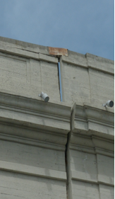
Another anomaly caused by the fault creep at this location cannot be corrected so easily. When you look up to the concrete tunnel arch right above the ground cracks you will see that the arch is separated vertically into two sections. When the concrete was poured during the reconstruction, the two sections were flush with each other. But as of this writing the fault creep has moved them an inch or so past each other. The same creep has also put the metal plate covering the separation into the odd angle shown in figure 5.9.
Leave the tunnel entrance by entering the spectators area of the stadium along the walkway on the west side of the tunnel. This is the side toward the press box. Walk almost halfway around the playing field in a counterclockwise manner. Then make your way up the bleachers until you reach the uppermost benches of section KK. Catch your breath by taking a seat and enjoying the view across the playing field and up Strawberry Canyon to your east.
5.4 Section KK
As the reconstruction of the stadium was meant to significantly increase its seismic safety, nearly all traces that the creep of the Hayward Fault had imposed on the structure in the more than eighty years of its existence were erased. However, the stadium’s status as a historic landmark did not allow for the alteration of the exterior wall during the remodelling. Hence all of Galen’s original separation joints had to be left exactly as they were when the reconstruction began, no matter how severely they had been affected by the movement of the Hayward Fault. We already saw one example of such a joint on the north side of the stadium at stop 5.2 . But nowhere else has the fault left a clearer mark than at the rim of the exterior wall in section KK. Since the original opening of the stadium the two sections of the wall here have separated and rotated significantly, leaving a 6-7 inch wide gap at the top. This gap is still clearly visible today. The landmark rules for non-altering the appearance of the stadium were so strict, that engineers even had to leave in place the weather beaten, rusty metal plate, which had been covering the gap for decades.
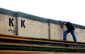
When comparing the gap in the wall here on the south side of stadium with the movement at the corresponding expansion joint on the north side near section XX at stop 5.2, one notices a significant difference. There the separation was 1.5 inches at best while the gap in section KK is at least 7 inches wide. Why is there such a difference? There is no clear answer, but several factors may come into play. One possibility is that the foundation of the stadium in these two sections reached down to different depths and hence into different rock types. They in turn may respond differently to the shear exerted by the creep. It is more likely, however, that the Hayward Fault does not creep at the same rate everywhere in this area and that the creep is not uniformly distributed along the fault. While the creep is clearly noticeable in and around the stadium and further south on Dwight Way (stop 7), there are no traces that the fault is currently creeping between these two locations.
From the rim walk straight down and leave the bleachers area through the exit immediately below section KK. Once through the exit you have reached the concourse level. Turn right and walk along the concourse until you reach the walls of the new press box. This is our stop 5.5.
5.5 Concourse Level
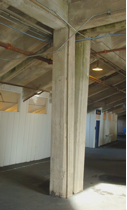
While walking along the concourse level, compare today’s solid concrete construction and the size of the columns with the columns before reconstruction as shown in figure 5.12. Then each column had a footprint of approximately one square foot. Today’s supports are much bigger and contain the appropriate rebar layout for maximum seismic resilience.
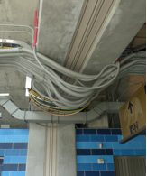
While looking up at the “ceiling” of the concourse you will notice several places where the lifelines (power, water, waste water, communication) are put in flexible conduits. This was done to give the pipes and cables enough flexibility to prevent them from rupturing during earthquake induced shaking. Such flexible conduits did not exist in the “old” stadium.
Wherever you see these flexible conduits “dangling” from the ceiling, you will also notice a flexible plastic cover between the concrete. This plastic has no structural role. Instead it was installed to cover the space between two separate sections of the stadium support structure. Similar to Galen’s original concept, the “new” stadium was also build in sections, each of which can move independently during an earthquake. This is supposed to make the stadium less rigid and more flexible, which will help mitigate damage due to seismic shaking.
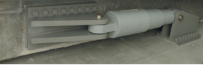
For the same reason the new pressbox is structurally completely separated from the rest of the stadium. It can move independently during earthquake shaking. To reduce the overall level of shaking a total of 16 massive hydraulic dampers have been installed between the various sections of the stadium and also between the press box and the rest of the stadium. They act like shock absorbers in a car. Each damper contains a silicone fluid which reaches its best damping when the shaking velocity is highest.
From the concourse level walk straight out Gate 6 (south gate) onto the parking lot at Prospect Court. Just before you walk through the gate, stop for a moment and look back at the exterior wall of the stadium. Under the proper viewing angle, you will see the sky through the gap at section KK, as shown in figure 5.10.
5.6 Prospect Court Parking Lot
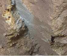
In preparation for the reconstruction geologists dug several trenches along and across the Hayward Fault in the vicinity of the stadium. One 80 ft long and about 20 ft deep trench was excavated perpendicular to the fault at the southern end of this parking lot near today’s pedestrian crosswalk. The goal of the trenching was to pinpoint the exact location of the active fault trace and to study its most recent seismic history. During the excavation the researchers encountered several areas in this trench, similar to the one pictured in figure 5.15. It shows how an active fault trace looks underground: The greyish material is what geologists call fault gouge. It is essentially a rock which is ground into a fine powder by the constant movement of the two flanks of the fault. In addition, the arrow in the picture points to striations in the rock. These are also caused by fault creep, like the grooves left behind when one uses rough sandpaper on a shiny piece of metal.
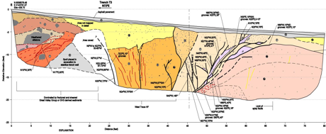
When trenching across active faults researchers usually put together their findings in maps of the walls of the trench, like the one shown in figure 5.16 for the south wall of the trench at Prospect Court. The various colors depict different kinds of sediments and soil found in the trench. The information relevant to this tour are the many black lines in the map, which look somewhat like roots growing underground. These lines mark active traces of the Hayward Fault like the one shown in figure 5.15. This again is proof that an active earthquake fault is not just a single straight line, but a complex zone of cracks and fault planes, which can extend over a large area. Hence, it is not surprising that different researchers found different strands of the Hayward Fault as depicted in figure 1 in the Introduction.
After it yielded its results, the trench was backfilled, paved over and is no more visible.
We are now leaving the stadium area by walking south along Prospect Street. After about 750 ft turn left into Hillside Avenue which gently curves to the south. After about 150 ft the road narrows and you will reach an old stone arch bridge, where the street crosses Hamilton Creek. Stand on the bridge and look to the east (upstream). This is our stop 6 in figure 2.
