Interference
37 Interference in two dimensions
Interference in two dimensions
So far, this chapter has only examined interference along a straight line (to keep things simple). Real waves- like water waves, sound and light- exist in more than just one dimension. What does interference look like in two-dimensional world (like the surface of a lake) or in the three-dimensional world we experience light and sound in?
This section explores the interference pattern produced by two sources. The example is shown in two dimensions, but the math also applies to the real three-dimensional world. To see what interference looks like, check out this stunning photo of a bee making waves [1] on the surface of a pond. (Due to copyright restrictions, I can only provide the link to the picture).
Two point sources
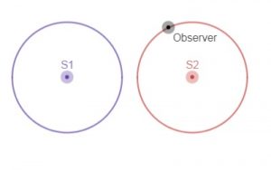
A point source is the simplest source of waves. Point sources (also called monopoles) send out circular waves (in two dimensions) or spherical waves (in three dimensions). What happens when two identical point sources make sound waves? The two sources have the same frequency, same amplitude and are in phase. Will there be interference? If so, where will there be nodes and antinodes? How can we figure out where those will be?

It might seem (at first glance) that there shouldn't be any destructive interference anywhere- after all, both sources are making identical waves at the same time. But there's a catch: sound (or any wave, for that matter) takes time to get from the source to the detector. Imagine yourself sitting somewhere in front of two speakers. Both speakers emit a short burst of sound at the same time. Will you hear both sounds at the same time? The answer is "no" (unless you happen to be sitting the same distance from both speakers). The sound from the nearer speaker will arrive a split second earlier than sound from the farther speaker. Both sounds start the journey at the same moment and travel at the same speed, but the sound from the far speaker has a slightly longer trip. This extra distance creates the time delay between the arrival of the two sounds at the listener.

This extra distance is important for interference. For example, the extra distance is half a wavelength, sound from the near speaker arrives half a cycle earlier than the sounds from the far speaker. As a crest made by the near speaker arrives at the listener, it meets the trough that was made by the far speaker half a cycle earlier. The sounds interfere destructively and the listener hears nothing. This destructive interference occurs at all locations that are half a wavelength closer to one speaker than the other. Destructive interference will also occur if the extra distance is [latex]1.5\lambda[/latex], [latex]2.5\lambda[/latex], [latex]3.5\lambda[/latex], etc. Each nodal line corresponds to a different amount of "extra distance." The result is a nodal line- a line along which the medium doesn't move. On a pond, nodal lines are visible as lines of still water- check out the "pond scene" about 4:25 into Veritasium's youTube video "The Original Double Slit Experiment." [2]
Constructive interference also occurs. For constructive interference, the extra distance must be exactly a whole number of wavelengths ( zero, [latex]1\lambda[/latex], [latex]2\lambda[/latex], [latex]3\lambda[/latex], etc.) (Remember that shifting a sine wave by a full wavelength has no effect on the sine wave.
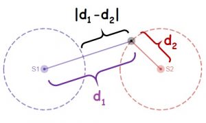
Summarizing: If the two sources are in phase, constructive interference will occur everywhere that's a whole number of wavelengths closer to the one speaker than the other. Mathematically:
[latex]|d_1-d_2|=m\lambda[/latex]
For sources in phase, destructive interference occurs everywhere that
[latex]|d_1-d_2|=(m+1/2)\lambda[/latex]
In these equations, [latex]d_1[/latex] represents the distance from the listener to one source, [latex]d_2[/latex] represents the distance from the listener to the other source, [latex]\lambda[/latex]is the wavelength of the sound and [latex]m[/latex] represents any whole number (including zero). Notice that it doesn't matter which source is which- the absolute value makes sure that the equation is based on the amount of extra distance.
The example above examined the case when the sources are in phase, but interference happens no matter whether the sources are in phase or not- there will still be nodal and antinodal lines. However, the nodal lines will be in different place. For example, if you redo the analysis above for speakers that are completely out of phase, you discover that there is a node along the line halfway between the two speakers.
Stop to think
- Sound plays through the speakers at a concert. Which do you hear first: sound from the left speaker or sound from the right?
- Can two sources that are in phase interfere destructively? Explain.
- Two in phase audio speakers 200 cm apart the same pure tone (wavelength = 50 cm) at moderate loudness and the speakers. What type of interference occurs at each of the following locations?
- Location A: 50 cm from both speakers
- Location B: 50 cm from one speaker and 75 cm from the other
- Location C: 125 cm from one speaker and 175 cm from the other
- Repeat the previous problem for two sources that are completely out of phase.
Interference patterns
The location and number of nodal and antinodal lines in an interference pattern varies depending on the spacing, phase and frequency of the sources. In general, the patterns with the most nodal lines come from speakers that are far apart that are producing high frequencies (and therefore short wavelengths). To see how this works, the reader is strongly encouraged to play with PhET's Sound simulation. [3] For best viewing, choose the “Two source interference” tab and set the amplitude to maximum. Nodal lines show up as gray lines in the region between the two speakers. Antinodal lines show up as stripes of alternating white and black region moving away from the speakers. You can move the listener around, change the frequency of the sources and view the changes. As you increase the frequency, there are more nodes and the nodes get closer together. As you decrease the frequency, there are fewer nodes and they are spaced farther apart. If the frequency is low enough, the situation gets very simple- there is either a single antinodal line or a single nodal line, depending on whether the sources are in sync or out of sync. PhET's Sound also shows that you can make interference patterns using just a single source and a wall. Choose the "Interference by Reflection" tab to explore.
An important ratio
If you play with the spacing between the sources and the wavelength enough, you'll notice that certain combinations of source spacing and wavelength result in identical interference patterns. For instance, two in-phase sources 40 cm apart emitting 10 cm waves will have the same interference pattern as two in-phase sources 20 cm apart emitting 5 cm waves.

While both source separation and wavelength both affect interference patterns, the key number is actually the ratio of source separation to wavelength:
[latex]s/\lambda[/latex]
(The distance between the sources is represented by the letter [latex]s[/latex]). A separation-to-wavelength ratio of four means the sources are four wavelengths apart (like the sources in the diagram). The number of nodes (or antinodes) in an interference pattern is roughly double separation-to-wavelength ratio:
[latex]N\approx 2s/\lambda[/latex]
The actual number of nodes and antinodes could be one higher or lower than [latex]2s/\lambda[/latex], depending on the phase of the two sources.
Stop to think
- Two sources 400 cm apart emit pure tone with a wavelength of 10 cm. What are some other distance and wavelength combinations that could produce the same interference pattern?
- Two sources 400 cm apart emit pure tone with a wavelength of 10 cm. About how many nodes are produced?
- Is it possible to have an interference pattern that has no nodes? Under what circumstances?
Interference patterns and music
The example above shows how two identical pure tones interfere. Music consists of many frequencies all at once, but the results above still apply. At any given location, some frequencies will interfere constructively and others will interfere destructively. Theoretically, you get music with music frequencies. In practice, we rarely notice these missing frequencies. Keep in mind that we have two ears, each at different locations separated by roughly 20 cm. Keep in mind also that our brain is pretty good at replacing missing information.
Interference patterns have one important implication for setting up stereo systems. If you hook up one of the speakers backwards, the two speakers will be out of phase. This will create a nodal line for all frequencies along the center line between the two speakers.
Interference and sources of sound
Many real world sources of sound aren't point sources. Audio speakers are an excellent example. Most speakers have a paper (or plastic cone that moves back and forth. As the cone moves forward, air in front of the cone is compressed (and air behind it is stretched). As the cone moves backward, the situation is reversed. Unless you block the sound coming out of the back of the speaker, the speaker acts like two out of phase point sources that are very close together. A source that behaves like two point sources that are close together is called a dipole source, or dipole (for short). At low frequencies, some boxed speakers act like monopoles. Sources that act like four monopoles close together are called quadrupoles. Tuning forks are an example of a quadrupole source. Dan Russell's website has excellent animations of the sound fields that different sources emit sound. [4]
Stop to think answers
- Depends on which speaker you are closer to. Sound from the closer speaker arrives first.
- Yes. If you are half a wavelength closer to one speaker than the other, sound from the one speaker arrives perfectly out of phase with sound from the other speaker. Sounds that left the speaker at the same time do not arrive at the listener simultaneously. The extra distance of half a wavelength creates a delay of half a period.
- Location A will have constructive interference because the listener is equidistant from both (in phase) sources. At Location B, sound from the closer speaker meets sound that was produced by the far speaker exactly half a period earlier: crests from the close speaker arrive in sync with troughs from the far speaker, resulting in destructive interference. Location C will also have constructive interference. The difference in distance is 50 cm- exactly one wavelength. At the listener, sound from the closer speaker meets sound that was produced by the far speaker exactly one period earlier. The shift of a full period puts the sound back in phase.
- Locations A and C will have destructive interference while B will have constructive interference.
- Any distance-wavelength combination with a 40:1 ratio will work- for example, sources 40 meters apart emitting sound with a wavelength of 1 meter.
- There will be roughly 80 nodes in the interference pattern. [latex]s/\lambda=40[/latex], so [latex]N\approx 2s/\lambda = 80[/latex]. The actual number of nodes could be 79, 80 or 81- depending on phase difference between the sources.
- Yes, if the distance between the two sources is half a wavelength (or less). The number of nodes is within one of [latex]2s/\lambda[/latex], so zero nodes is possible if [latex]s/\lambda \le 1/2[/latex].
Image credit
Two interference patterns with a separation-to-wavelength ratio of four. Created by Abbott using desmos.com
- Giuşcă, B. (2007, February 4). Waves made by the wings of a bee in a lake. Retrieved from https://commons.wikimedia.org/wiki/File:Ripples_waves_bee.jpg ↵
- Veritasium. (2013, February 19). The original double slit experiment. Retrieved from https://youtu.be/Iuv6hY6zsd0 ↵
- PhET. (no date). Sound. Retrieved from https://phet.colorado.edu/en/simulation/legacy/sound ↵
- Russell, D. (2013, November 21). Sound. Retrieved from https://www.acs.psu.edu/drussell/Demos/rad2/mdq.html ↵
