14 Working with Drawing Views – I
CHAPTER 14 WORKING WITH DRAWING VIEWS – I
This chapter introduces us to the third and final “mode” of Solidworks – DRAWINGS. As we all know, drawings are typically 2D representations of parts and assemblies. Although 3D models are becoming increasingly employed during manufacturing, 2D drawings are still used extensively during the manufacturing process. Drawings are very carefully controlled by an organization to ensure that the latest version (or “revision”) of the drawing is used by everyone in the process. This control process is called configuration management and you will certainly be exposed to it when you work in industry.
In the workflow followed by most organizations, 2D drawings are created after models and assemblies are created and finalized. Drawings are at the end of the process. Note that when using a 2D CAD system (like AutoCAD), drawings are pretty much what we are creating in the first place. Thus, we say that 2D CAD is “drawing-centric” while 3D parametric systems (like Solidworks and Inventor) are “model-centric”.
If you’ve had the displeasure of creating drawings in a 2D CAD system, you know how tedious it can be. It is particularly challenging to get everything scaled properly for printing and don’t even get me started on how cumbersome it is to dimension a drawing or even add notes! I think you’ll find that creating drawings in Solidworks is quite easy. When discussing drawings in this class, I often put a twist on the Rocket Mortgage “push button – get mortgage” ad by saying “push button – get drawings”. It really is that easy!
Please watch the overview video below before attempting any assignments requiring the creation of drawings. It covers how to start a drawing, using BC3 borders, creating the standard 3 orthographic views, adding an isometric view, changing the display style (to display hidden lines), adding centermarks and centerlines, creating a section view, editing the title block, adding notes and saving your drawing in PDF format. Some of these topics are covered in Chapter 14:
THE DRAWING MODE (page 14-2)
There are two basic ways to create drawings in Solidworks – generative and interactive. In the generative mode, we generate the drawings by “borrowing” the models or assemblies. This is very similar to how we “borrow” models to create assemblies. In the interactive mode, we sketch the drawing views using sketching tools. We will talk about and use the generative mode exclusively.
One thing to note here is that Solidworks employs what we call “bidirectional associativity”. This means that changes made in a model while in the Part mode are automatically carried forward into any assembly or drawing that model is used in. Additionally, if you make a changes to a model while in the Assembly or Drawing mode, the changes are also reflected in the model itself. Pretty cool stuff!
WORKING WITH BC3 DRAWING BORDERS (Not in Text)
Watch the following instructional video and then follow the attached guideline document to prepare your Solidworks set up to use pre-made BC3-specific drawing borders rather than the default borders that come pre-loaded in the software. Do this before attempting to create any drawings:
Click here to view the guidance document for preparing your system to use BC3 drawing borders: How to Install and Apply BC3 Drawing Borders
STARTING A DRAWING DOCUMENT (page 14-2)
To generate drawing views, you need to start a new drawing document. There are 3 ways to do this and they are discussed in detail in the textbook, so I will not go into detail in this guide:
- Use the Welcome – SOLIDORKS 2019 Dialog Box (page 14-2)
- Use the New SOLIDWORKS Document Dialog Box (page 14-4)
- From the Part/Assembly Document (page 14-4)
I rarely start a drawing directly from the Part/Assembly document. I normally use the New SOLIDWORKS Document Dialog Box (see Figure 14-3, Page 14-4 and below). This can be accessed by clicking on the New command icon. Then select the Drawings mode option and click OK.
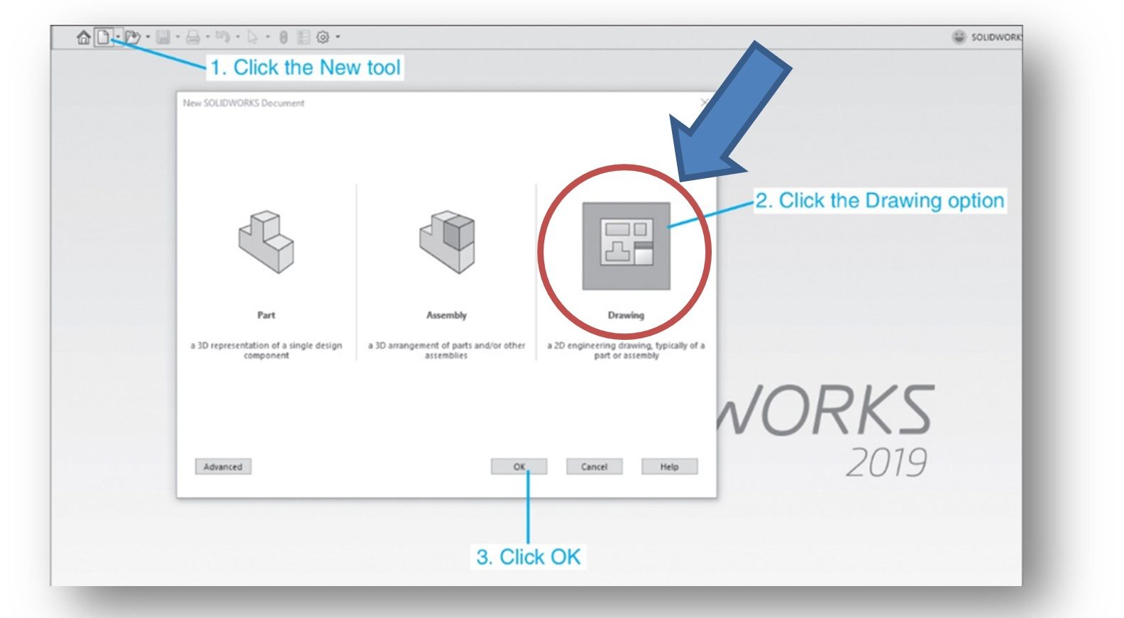
Once you click OK, Solidworks takes you to the Sheet Format/Size dialog box (see below):
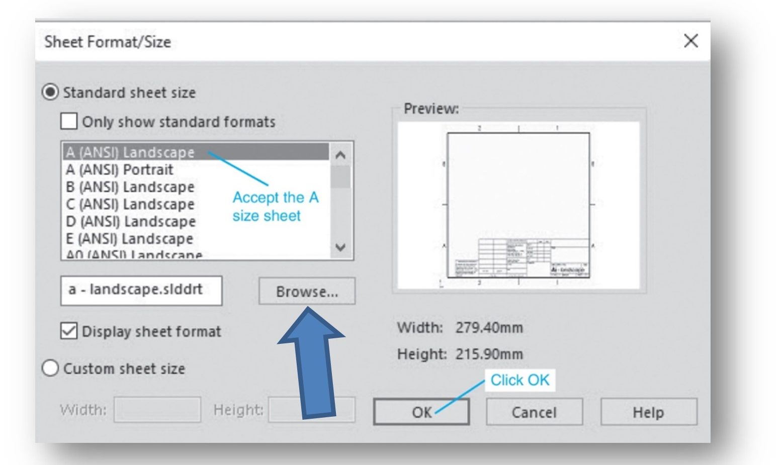
Here, you can select one of the default drawing sheets/templates that comes with Solidworks or you can select one of your own by clicking on the Browse… button. I typically tell you which drawing template to use for an assignment or test.
NOTE: Drawing “Sheets” in Solidworks are roughly equivalent to drawing templates in AutoCAD. We’ll go over how to do this a little later.
TYPES OF VIEWS (page 14-4)
From your previous experience with drawings, you know that there are many types of “views” that can be created. Solidworks allows you to create the following types of views. I’ve highlighted in RED the most commonly applied views:
- Model View – is used to create the base view in the drawing sheet. You can also generate orthogonal views (such as the front, top, left etc.) as the Model View. You can also generate an isometric view as the Model View. These are the primary views created in our drawings.
- Projected View – we do not use in this class
- Section View – is created by chopping away part of an existing view using a section plane to reveal internal features of the part or assembly.
- Aligned Section View – we do not use in this class
- Removed Section View – we do not use in this class
- Auxillary View – generated by projecting lines perpendicular (normal) to the specified edge of an existing view. Allows us to see the complete view of an inclined surface in true shape and size.
- Detail View – used to display the details of a portion of an existing view. You can select a portion of the parent view to detail. On doing so, the selected portion is magnified and placed as a separate view. You can control the amount of magnification applied.
- Break View – we do not use in this class
- Broken-Out Section View – we do not use in this class
- Crop View – we do not use in this class
- Alternate Position View – we do not use in this class
GENERATING STANDARD DRAWING VIEWS (page 14-7)
Generally, the standard views are the first views that are generated in the current drawing sheet. Standard views typically include the 3 principle views – front, top, right side. There are several methods for generating the standard drawing views.
IMPORTANT REMINDER — It is IMPERATIVE that the drawings you create are saved in the samefolder that you originally saved your model. Failure to do so will result in your drawings being disconnected from your model (never a good situation!).
NOTE: In the USA we ALWAYS create drawings that comply with the ANSI Drafting Standard, even if the dimensions are in millimeters!! Therefore, before starting and drawing, be sure to set the Document Property for Overall Drafting Standard to ANSI. This will ensure that your views are created using third-angle projection. It will also ensure that your dimensions are properly applied. You need to do this for every drawing you create.
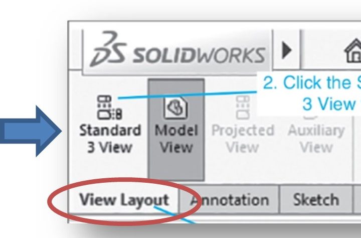
The tools used to create drawing views in Solidworks reside in the View Layout CommandManager:
GENERATING MODEL VIEWS (page 14-7)
I do not use the method described in this section. See the next section……
GENERATING THE THREE STANDARD VIEWS (page 14-10)
Because we typically create drawings with 3 orthographic drawing views, we normally select the Standard 3 View command from the View Layout CommandManager. This will allow you to create your drawing with the typical front, top and right-side views.
The Standard 3 View PropertyManager will be displayed (Figure 14-8, Page 14-11 and below):
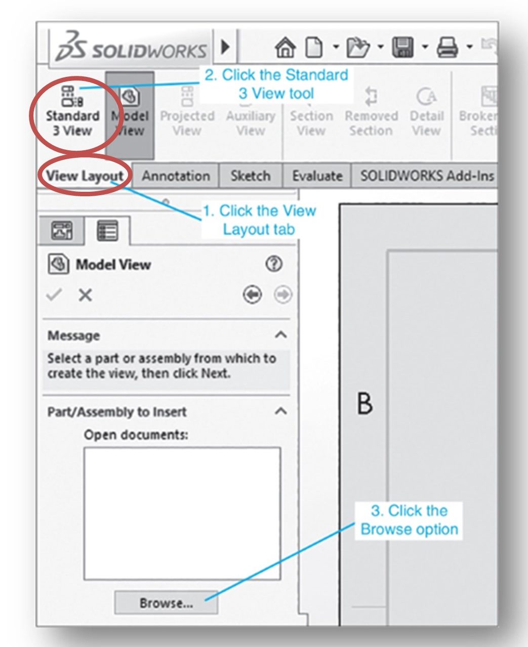
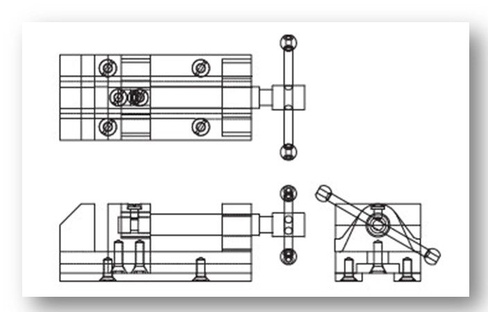
If not already open, you will have to browse to the folder location where you saved the part model (or assembly) you wish to create a three-view drawing for. As soon as you double-click on the part or assembly document you wish create the drawing for, the three standard views will be automatically created. Below are how the three views were generated for the Bench Vise (Figure 14-9, Page 14-11 and below):
Your three views will be created at the default scale that exists on the sheet you selected earlier. You can change the scale of the views at any time after they are created.
Note that the three views are “locked together” in order to maintain the proper orthographic alignment between the views such that all the features properly line up in the views. For example, the top view will be locked horizontally with the front view and the right view is locked vertically with the front view. We take great pains in a 2D CAD system to achieve this alignment – in Solidworks we get it for free!! You can move the views individually by selecting and dragging the view using your left mouse button to achieve the desired spacing between the views, but you will not be able to move them such that they become mis-aligned. See the second “TIP” box on Page 14-12.
Note that by default, the views will not have hidden lines or center lines except for the centermarks (cross-hairs) associated with hole centers. Once your three views are in place, you can go about adding hidden lines from one or more of the views. You can also add centerlines to features such as holes and slots. This is covered in Chapter 15.
GENERATING STANDARD VIEWS USING THE RELATIVE VIEW TOOL (page 14-12)
I do not use the method described in this section.
GENERATING STANDARD VIEWS USING THE PREDEFINED VIEW TOOL (page 14-14)
The Standard 3 View tool will create front, top and right views only. Typically, that is sufficient. However, sometimes additional views are needed. For example, often we want to display an isometric view of the part or assembly to aid in the interpretation of the 2D views. To add additional views beyond the standard 3 views, you can use the Predefined View tool. This tool can also be used to insert the 3 standard views as well.
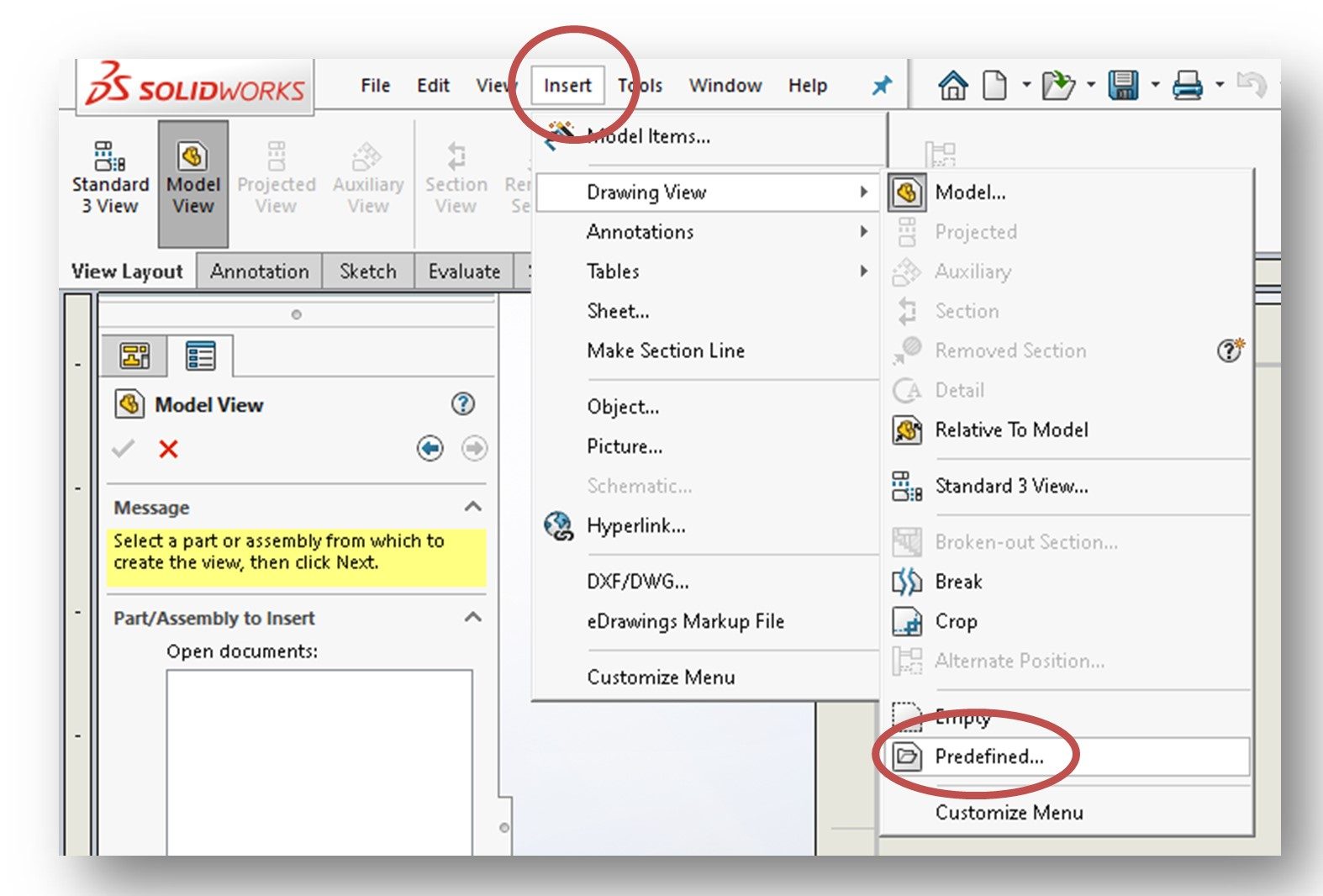
To access the Predefined View tool, you need to select Insert from the Solidworks Menu at the top of the screen. Then select the Drawing View option and then the Predefined… option (see figure below):
An empty view will be attached to your cursor. Left-click to approximately place the view (you can move it later if needed). An empty rectangle defining the new view will be placed in the drawing and the Drawing View PropertyManager will open (see Figure 14-13, Page 14-14 and below):
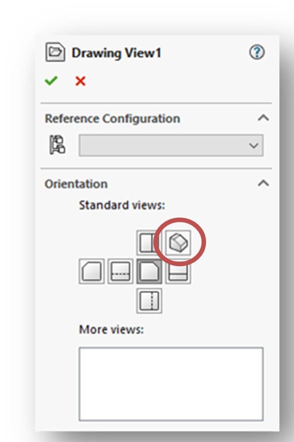
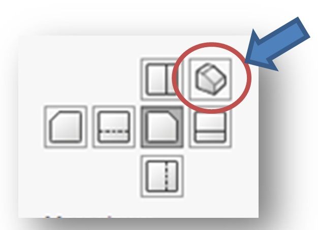
This PropertyManager allows you to select what view this new view will be (normally we are inserting an isometric view, so click the isometric view icon located in the Orientation roll-out (see figure below):
Now, you will need to specify what part or assembly you want to pull the view from. To do this, click the Browse button located in the Insert Model roll-out. Then browse to the location of the part or assembly you wish the view to be taken from. Double-click on the applicable document. Then click the green checkmark at the top of the PropertyManager to accept your inputs. The appropriate view should now be displayed in your drawing. (see below):
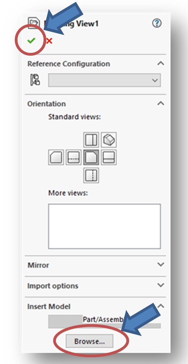
NOTE: You would need to repeat this process for every new predefined view you want to add. But again, we normally do not use this tool to add the principle views (top, front, right, etc.). We normally only use this tool to add an isometric view to the drawing. If you do add a principle view, you would need to “align” it using the routine described on Page 14-14.
GENERATING DERIVED VIEWS (page 14-14)
Any view that is not a predefined view is called a derived view in Solidworks. Theseviews are derived (“generated”) from one of the views already placed in the drawing. Derived views include sections, details, auxillaries, and more. We are only going to talk about sections, details, and auxillaries.
GENERATING PROJECTED VIEWS (page 14-16)
I do not use the method described in this section.
GENERATING SECTION VIEWS (page 14-17)
You all know what a section view is. Some parts have internal surfaces that are not directly visible in the standard orthographic views. Section Views can be used to peer inside a part and expose these surfaces.
NOTE: Section views do not include hidden lines!!
Creating section views on a manual drawing (or even in a standard 2D CAD system like AutoCAD) can be very tedious. Thankfully, Solidworks makes this process very simple.
Let’s start out with a quick review of sections:
To create a section view, the part is “cut” by a Cutting Plane represented on the drawing by a Cutting Plane line (yes, that line type is in the Alphabet of Lines!). Material to one side of the cutting plane is removed, thus exposing the internal surfaces of the part. Each end of the cutting plane line is labeled with the same letter and the resulting section view is labeled as a view with those letters (ie., View A-A):
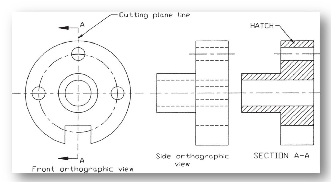
Subsequent sections and cutting plane lines would be labeled with the next letter in the alphabet.
Any material that is cut when the section is created is “hatched” using Section Lines (yes, those are part of the Alphabet of Lines, too!). There are many different hatching styles. Most different types of engineering materials have their own distinct hatching pattern – including metals, concrete and even wood. Here are some examples:
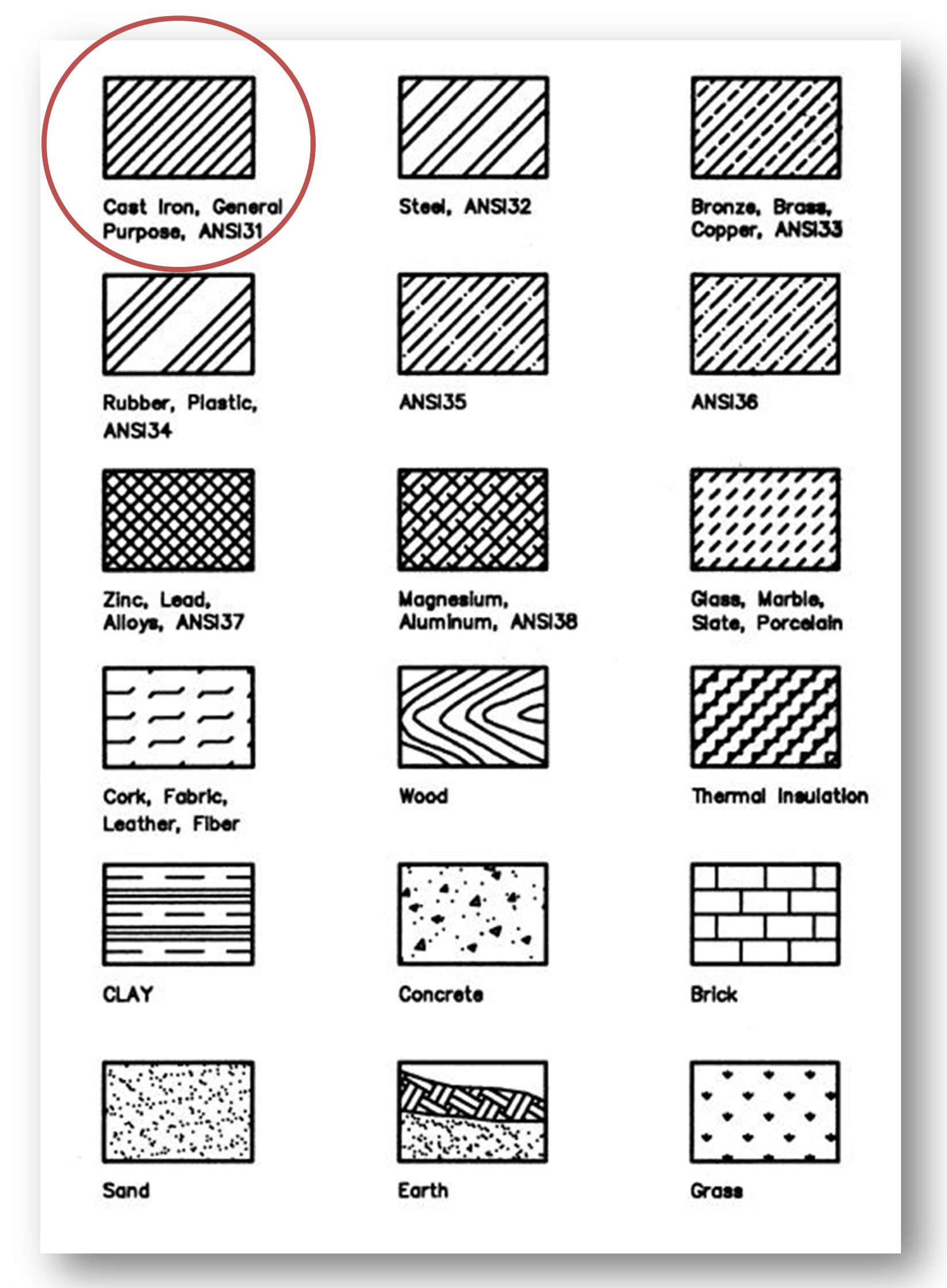
However, the general style is evenly spaced parallel lines drawn at a 45-degree angle. This style is defined as ANSI 31 and is automatically applied by Solidworks whenever a section is created. You can select any hatch pattern for your section views that you want, but for mechanical parts we typically stay with the default pattern.
See MODIFYING THE HATCH PATTERN IN SECTION VIEWS on Page 14-40 for more information.
Drawing a Section View Using Solidworks:
NOTE: Section views are derived views and therefore can only be generated after a standard view is already placed into the drawing.
Section views are created using the Section View tool found on the View Layout CommandManager (see figure below):
The Section View tool can be used to create both full and half sections. See examples shown in Figures 14-17 (Full Section) and 14-18 (Half Section) on Pages 14-17 and 14-18, respectively.
CREATING HORIZONTAL /VERTICAL FULL SECTION VIEW (page 14-18)
To create a full section, you first “activate” the view in which you wish to create the sectioning line (cutting plane line) by left-clicking on the view. Once the view is activated, select the Section View tool from the View Layout CommandManager as described above. The Section View Assist PropertyManager will be displayed (Figure 14-19, page 14-19 and below):
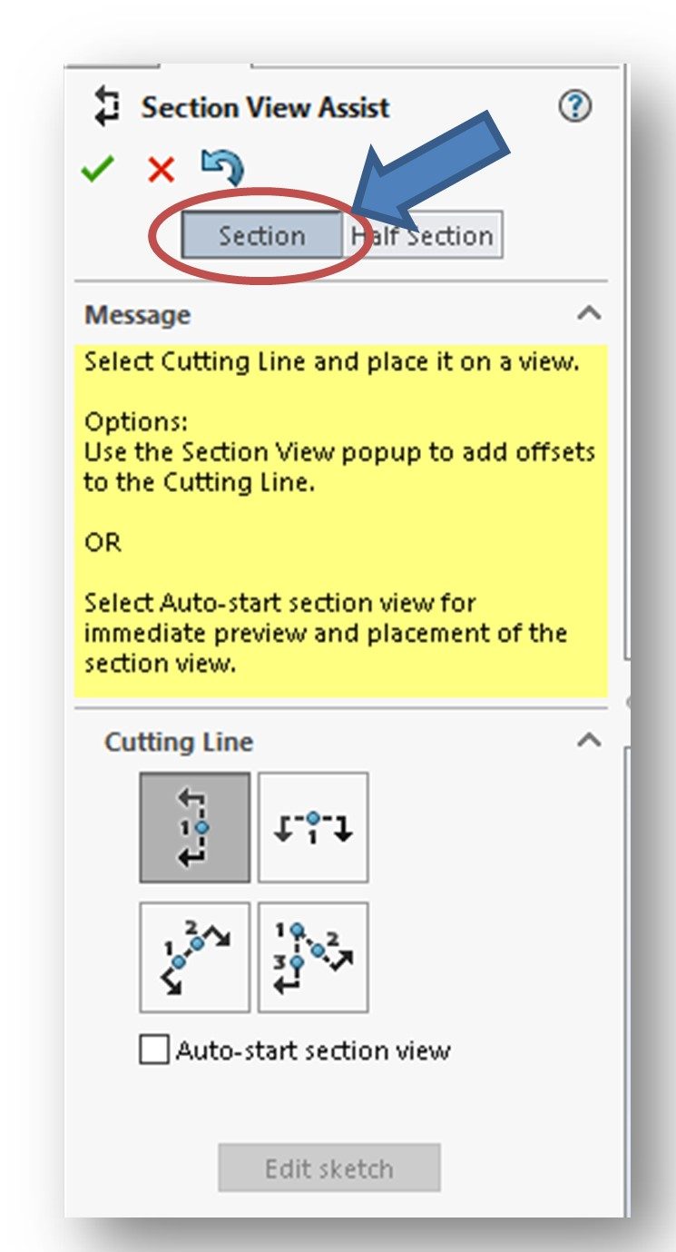
The Section option button at the top of the PropertyManager is selected by default. This means you will be creating a full section. Select the Half Section button if you wish to create a half section (see below):
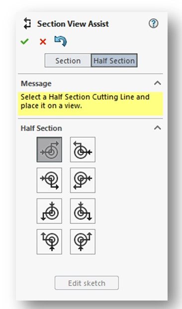
NOTE: Depending on how the Solidworks default is set, either a horizontal sectioning line or a vertical sectioning line will be attached to the cursor. (I believe our default will result in a vertical sectioning line although the textbook indicates that a horizontal sectioning line will be selected). IN any case, you can select either of the four options in the Cutting Line roll-out of the PropertyManager.
The sectioning line will appear in the view you previously selected for sectioning. (See figure below):
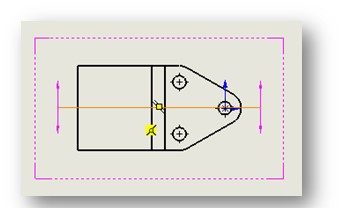
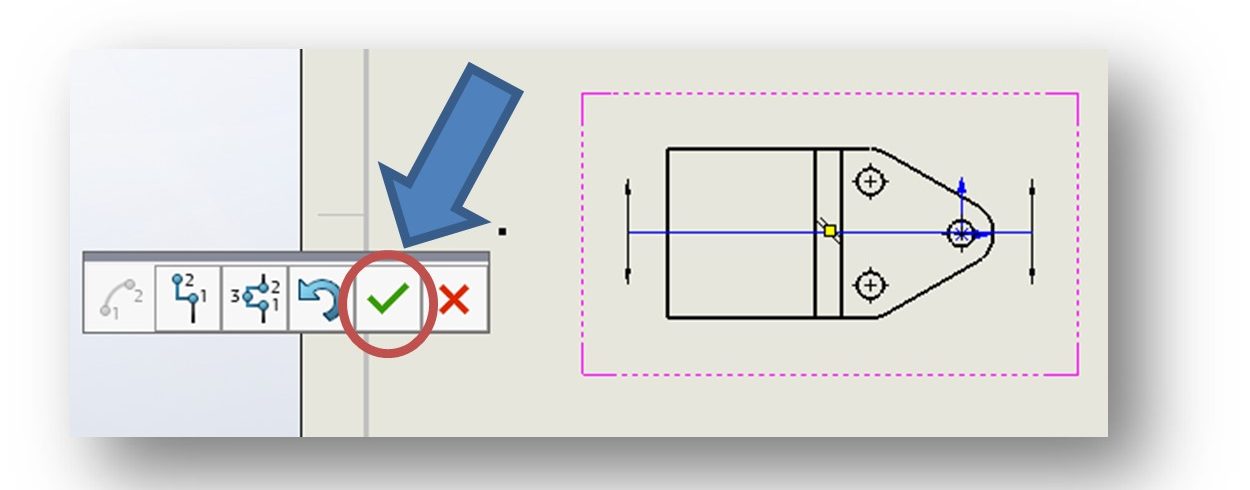
You can use your cursor to position the cutting/sectioning line. Note that a horizontal cutting/sectioning line can only be moved up and down while a vertical sectioning line can only be moved left and right within the view. Once in place, click your mouse’s left mouse button to accept the position. A fly-out menu will appear. If you are happy with the section, click on the green check mark to confirm your cutting/sectioning line. (See figure below):
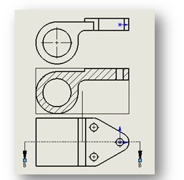
Once you click the checkmark, a “permanent” cutting plane line will be placed in the drawing view and the section view created by it will appear (See figure below):
Also, the Section View PropertyManager will be displayed for your specific section. (See figure below):
At this point, the section view can be moved either up and down (if a horizontal section was taken) or right and left (if a vertical section was taken). Place the section view where you want it in the drawing.
NOTE: Often a section view is intended to replace one of the standard views. If this is the case, you can delete the standard view and just position the section view in its place after deletion. See DELETING SECTION VIEWS on Page 14-39.
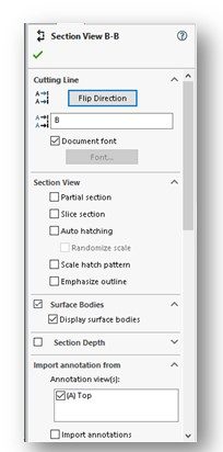
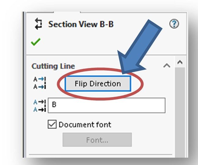
Sometimes you need to “flip” the direction of the section in order to get the section view you want. To do this, click the Flip Direction button located in the Cutting Line roll-out of the Section View Property Manager (see below). The section view in the drawing will be modified as will the direction of the arrows on the cutting plane line.
Here a little review addressing the direction of the arrows on the cutting plane line and how the section view is created:
NOTE: The arrows on the cutting plane line always point AWAY FROM the section view. Think of the arrows as being the direction your eyes look to see the section view.
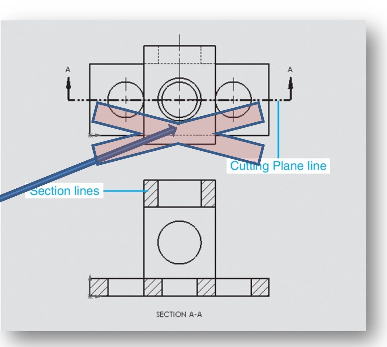
The large “X” in the above figure overlays the half of the part to be removed to reveal the section.
You can also use the Section View PropertyManager to change the letters to be placed on the arrows of the cutting plane line. The first section you create should always be A-A, the second B-B and so on. The system sequentially letters each section you create whether you keep that section in your drawing or not, so you often need to manually adjust the letters.
GENERATING ALIGNED/AUXILLARY SECTION VIEWS (page 14-20)
Skip this section.
CREATING HALF SECTION VIEWS (page 14-21)
Similar to the process for a full section. Read over. We probably won’t be doing a half section view in this course.
CREATING THE SECTION VIEW BY USING SKETCH LINES (page 14-23)
Skip.
CREATING THE SLICE VIEW (page 14-23)
Skip.
GENERATING THE SECTION VIEW OF AN ASSEMBLY (page 14-24)
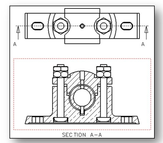
Yes, we can section a view of an assembly (See Figure 14-29, page 14-25 and below). Read this section over. The process is similar to how we section a part. There are some specific “rules” you need to be aware of (ie., not sectioning fasteners). Again, Solidworks makes abiding by these “rules” pretty easy. Don’t sweat over this section too much.
GENERATING REMOVED SECTION VIEWS (page 14-27)
Skip this section.
GENERATING AUXILIARY VIEWS (page 14-28)
Auxiliary Views are orthographic views that are used to show true-shaped views of a slanted (inclined) surface (see below). Like detail views, these are supplemental views. Auxiliary views are the only way to depict slanted surfaces as true shape and size. Basically, they are created by projecting sight lines perpendicular to the slanted surface up to a projection plane that is parallel to the slanted surface.
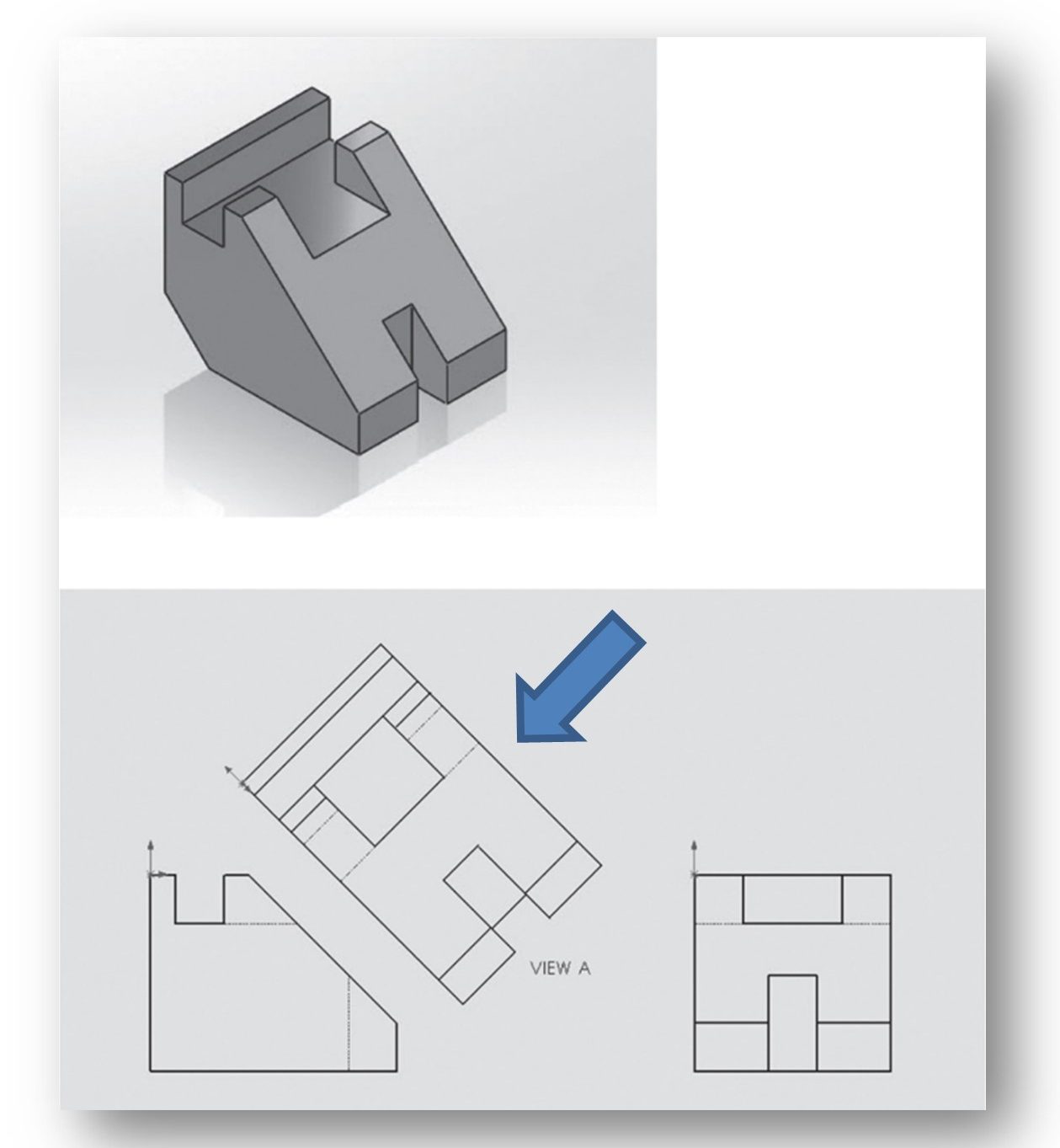
Creating auxiliary views on paper or in a traditional 2D CAD system (like AutoCAD) can be quite painful. Luckily, Solidworks makes this task pretty easy. To do so, we use the Auxiliary View tool located on the View Layout CommandManager (see figure below):
We are not likely to generate any auxiliary views in this class, but I think it’s a good idea to familiarize yourself with how to do it. Solidworks makes the process quite easy, especially compared with how you have to do this is in AutoCAD! Please read this section over, but don’t dwell on it.
GENERATING DETAIL VIEWS (page 14-30)
A Detail View is used to help clarify a specific area within a drawing view. It is not a principle view – it is supplemental to the principle viewsYou must create a principle view before you can create a detail view – it is a “derived” view. A new view is created for the detail which you can place as you wish on the drawing (it is not aligned/locked to any of the principle views).
Usually the area to be clarified is magnified (shown at an enlarged scale) so that the details are easier for the reader to see. By default, Solidworks doubles the scale of the parent view out of which you are creating the detail. You can change the scale to whatever you want.
Detail views are created using the Detail View tool found on the View Layout CommandManager (see figure below):
Once the Detail View tool is activated, the Detail View PropertyManager will be displayed (see Figure below):
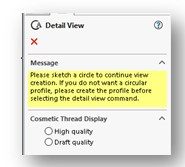
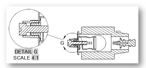
Also, your cursor will take on the look that it has when you’re using the Circle sketching command – that’s because you basically use a circle to enclose/define the area you wish to include in the detail view. You need to get the circle’s center-point in the right place. Note that we always use the “Broken Circle” style for details here at BC3. See the example above.
Once you “draw” the circle, the detail circle will be drawn on your drawing view and the detail view will be attached to your cursor. You and drop the detail view anywhere in your drawing by dragging it to its final location and clicking the left mouse button.
In addition, the Detail View PropertyManager for your specific detail view will be displayed (see Figure 14-41, Page 14-30 and below). It can used to change attributes of the detail view you just created:
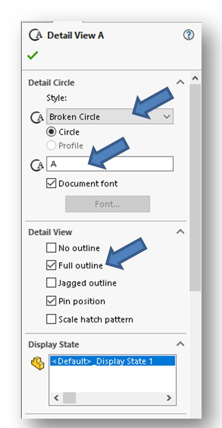
First, make sure your circle is a Broken Circle type. This is set by making the appropriate selection in the Detail Circle fly-out of the Detail View PropertyManager. The default selection is “Per Standard”. Use the drop arrow to reveal the options and select “Broken Circle”.
Next, make sure your detail circle is a full outline (a complete circle) in the detail view. We do this by selecting the Full Outline box in the Detail View fly-out of the Detail View PropertyManager.
Also, detail views are assigned a letter by Solidworks – it can be changed using the Detail View PropertyManager. Your first detail view should be “A” and the second “B” and so on. As with section views, the system sequentially letters each detail view you create whether you keep that detail in your drawing or not, so you often need to manually adjust the letters.
Finally, you can also use the Detail View PropertyManager to change the scale that the detail view is displayed at.
We don’t use this tool very often in this class, but detail views are pretty common out in industry.
GENERATING CROP VIEWS (page 14-33)
Skip.
GENERATING BROKEN VIEWS (page 14-33)
Skip.
GENERATING ALTERNATE POSITION VIEWS (page 14-35)
Skip.
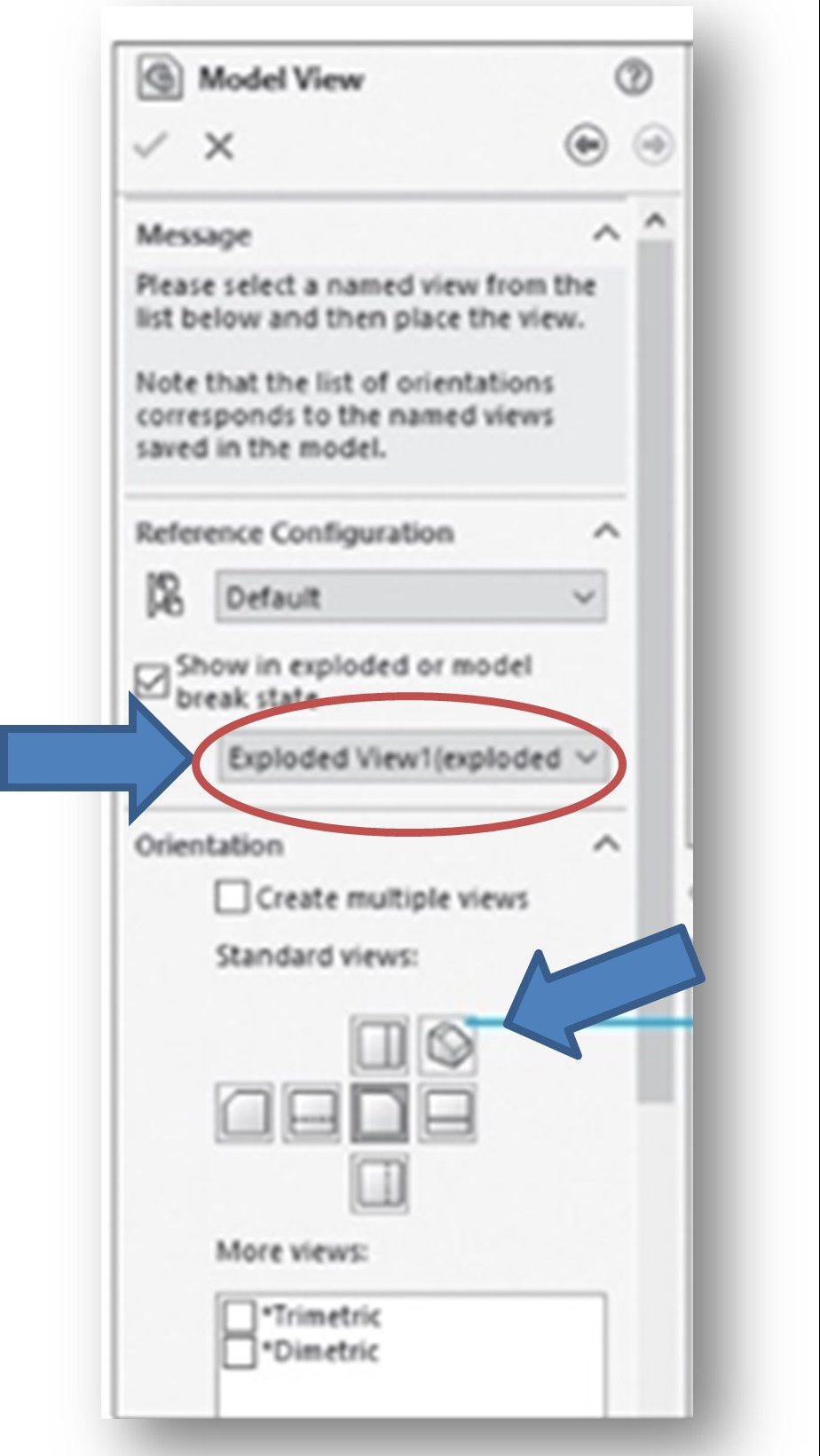
GENERATING DRAWING VIEWS OF THE EXPLODED STATE OF AN ASSEMBLY (page 14-37)
Note that you must have already created and saved an exploded assembly state before starting this new drawing as you need to “borrow” that view to make it appear in the drawing. Creating an exploded state of an assembly was covered at the end of Chapter 13.
Exploded assembly drawings are typically comprised of an exploded view in isometric orientation and a collapsed assembly view also in isometric orientation. To create the exploded view, we use the Model View tool located in the View Layout CommandManager (see figure below):
You need to make sure the “Exploded View” and the “Isometric option” are both selected in the Model View PropertyManager. (see figure below):
Otherwise, you create the the exploded view drawing exactly the same as any other drawing. We will cover how to annotate an exploded view drawing in Chapter 15 by adding “balloons”, Bills of Materials (BOMs), notes, etc.
WORKING WITH INTERACTIVE DRAFTING IN SOLIDWORKS (page 14-38)
We don’t use the interactive mode in this class.
EDITING AND MODIFYING DRAWING VIEWS (page 14-38)
You can perform a variety of editing operations on your drawings. For example, you can change the scale of one or more of the views, delete views, etc.
Recommend you just read this section over, particularly about how to delete a view. We’ll go over more about editing your drawings in Chapter 15.
MODIFYING THE HATCH PATTERN IN SECTION VIEWS (page 14-40)
I’m not quite sure why Tikcoo plopped this topic out here at the end of the chapter. This really should have been covered back when we discussed section views.
Anyway, you’re probably not going to have to change the hatch patter of a section view in this class, but you should read this over nonetheless.
CONGRATULATIONS! YOU ARE DONE WITH CHAPTER 14!
