2 Drawing Sketches for Solid Models
CHAPTER 2 DRAWING SKETCHES FOR SOLID MODELS
THE SKETCHING ENVIRONMENT (page 2-2)
From Chapter 1 we remember that models are created by combining features. Features can be sketched (this is what Chapter 2 is all about), placed (this is Chapter 5 & others), or derived.
Watch this YouTube video to get a quick overview of working with Solidworks:
Placed features are created without drawing a sketch first. For example, we can directly apply (ie, “place“) a fillet feature on a solid model. Same goes for a hole feature. And, this is exactly what we do if we can because applying features is usually much easier than creating the basis for them in a sketch first.
So, sketched features require us to create a sketch first. And creating a sketch is always the first step in creating a part model. This first sketch creates what is called the “base feature”. Its like the foundation of house – other features are then added to the base feature to complete the model. It is the modeler’s responsibility to decide what the base feature should be for a given design. Usually it’s a pretty obvious choice, but sometimes it takes a bit of thinking to decide what to do first. The more you model, the better you get at selecting the base feature. In this chapter, you will learn to create the sketch for the base part using various sketch tools.
A sketch is simply thought of as the basic contour for a feature. Look over the Spanner Wrench example shown in Figures 2-1 thru 2-3 on page 2-2. It isn’t the best example of a typical base feature sketch, but it gets across the idea of what a sketch is.
The sketching environment can be invoked at any time when you are in the PART or ASSEMBLY mode. You just have to tell Solidworks that you want to draw a sketch of a feature and then tell it which plane you want
STARTING A NEW SESSION OF SOLIDWORKS (page 2-3)
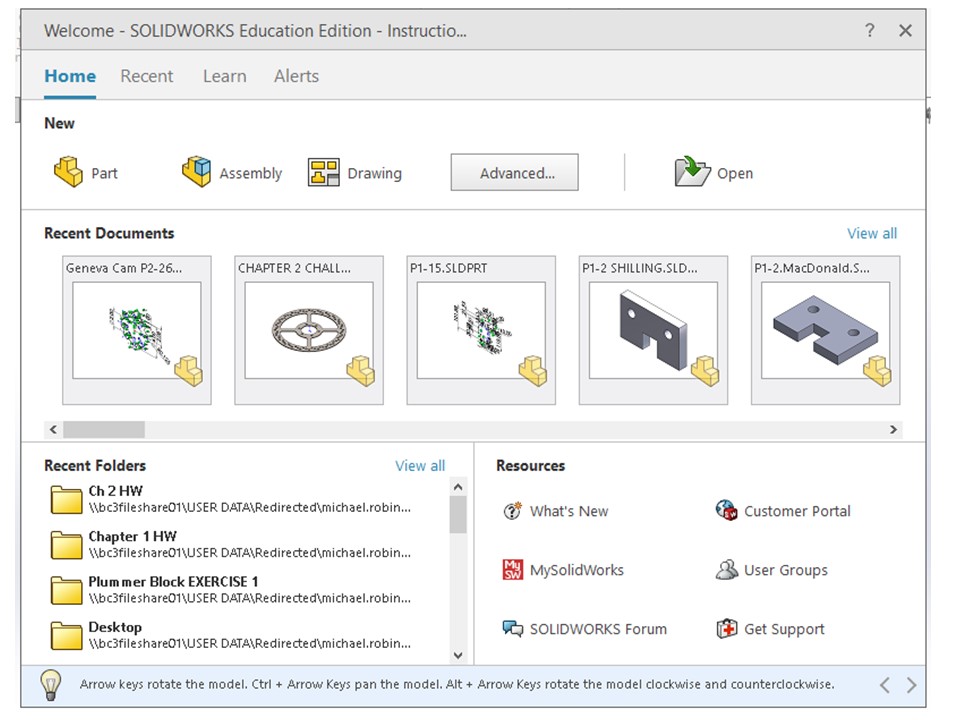
Read this section through. Note that you are likely to see the license agreement acknowledgement dialog box every time you launch Solidworks – our IT Department isn’t quite sure why this happens, but just be aware that it does.
It is also noted that the author says to collapse the Welcome – Solidworks 2019 dialog box, but in reality if you are just planning to start a new part, assembly or drawing you can do it right from this dialog box.
You can also access the Welcome – Solidworks 2019 dialog box by clicking on the Resources tool icon in the Task Pane (see next section)
TASK PANES (page 2-3)
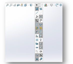
Whenever you start a Solidworks session, the Task Panes are displayed on the right-hand side of the drawing screen.
See Figure 2-5 on Page 2-3 and below:
You can read this entire section over, but we really only use the Resources Task Pane (the icon at the top that looks like a “house”) in this class (page 2-3). Clicking on this icon opens the Welcome – Solidworks 2019 dialog box. See Figure 2-6 on Page 2-4. The other Task Panes (Design Library, File Explorer, View Palette, Appearance, Custom Properties) are not really used in this class. You can just skip over these sections.
STARTING A NEW DOCUMENT IN SOLIDWORKS 2019 (page 2-7)
From the Welcome – Solidworks 2019 dialog box (see Figure 2-6 in previous section), you can either start a new part, a new assembly, or a new drawing. These are, of course, the three modes of Solidworks we discussed in Chapter 1. See Figure 1-3. Click on the PART icon to start a new part!
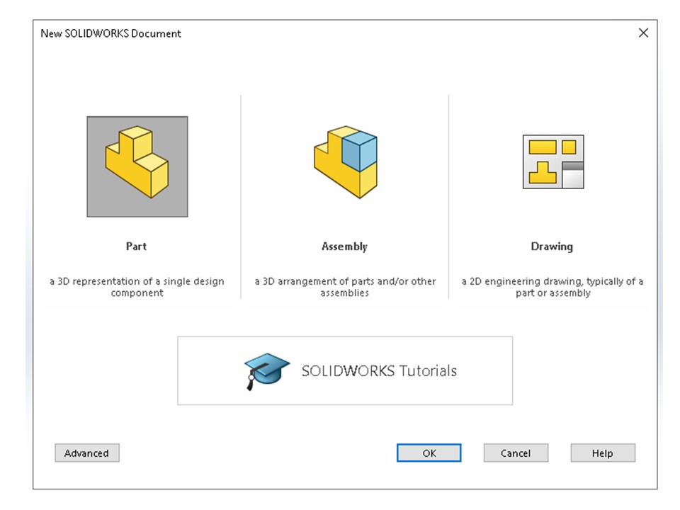
You can also start a new document from the New Solidworks Document dialog box (see below). This dialog box can be invoked by clicking on the New button on the Menu Bar. Click on the PART icon to start a new part!
UNDERSTANDING THE SKETCHING ENVIRONMENT (page 2-8)
Okay, so you’ve gotten to the point that you can start up Solidworks and begin a new part. Great! But now what the heck do you do?? This section helps to get you on your way to modeling a part.
Here’s the bottom line – all designs start out with what we call a base feature. This is what we build all the other features of the part on. Using a manufacturing analogy, this would be like the raw stock we start out with when we machine a part on a mill.
We start out by using the sketching tools of Solidworks to sketch the base feature in 2D. These sketch tools are very similar to the sketch tools you find in 2D CAD programs like AutoCAD.
Watch the YouTube video below to get a quick introduction to sketching in Solidworks:
To invoke the sketching environment, choose the Sketch tab from the Sketch CommandManager. See Figure 2-8 on page 2-8 (also shown below). [NOTE: At the top of page 2-8, the author goes on into adding the Sketch button to the Menu Bar. You can just ignore all that.]
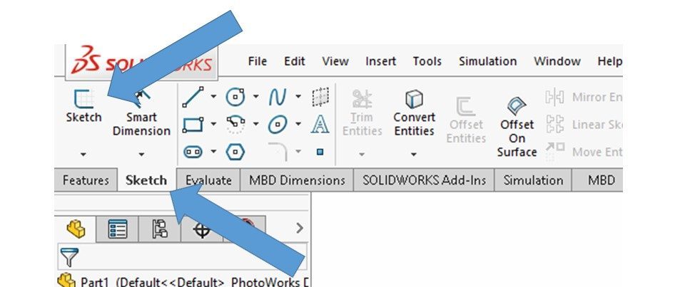
Once you click on the Sketch tab, the Sketch CommandManager (see Figure 2-8 and above) will be displayed above the drawing area. The Sketch CommandManager was discussed in Chapter 1. This is your starting point for creating a sketch. Now, you click on the Sketch command button (see Figure 2-8 and above) to start the sketching process.
When the Sketch command button is pressed, the Edit Sketch Property Manager (Figure 2-9) will be visible on the left-hand side of the drawing area:
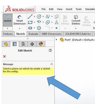
The message highlighted in yellow in the Edit Sketch Property Manager says “select a plane on which to create a sketch for the entity”. That’s the next step in the process! Which plane you use as the sketch plane is based on the requirements of the design – we’re not going to get into that right now. But the fact of the matter is that you must select one of the three principle planes upon which to draw your first sketch (because there isn’t anything else to use as a sketch plane at this time!):
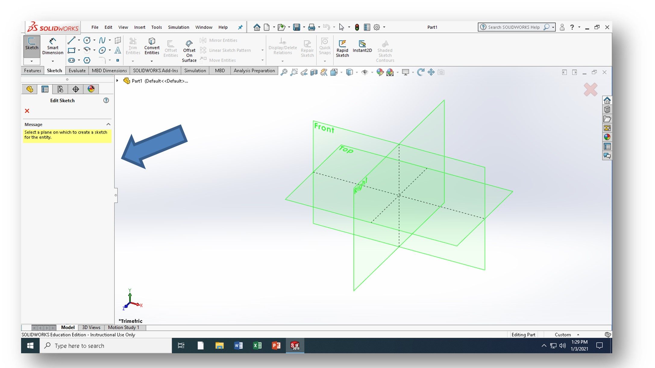
If you “hover” your cursor over the planes shown in the drawing area, the border will turn red/orange. That means you can select that plane by clicking on it in the drawing area. Once the plane has been selected, the default screen of the part sketching environment is displayed (see Figure 2-10 and below):
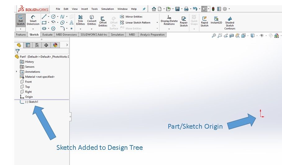
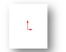
Note the two red arrows in the middle of the screen – where the arrows meet is called the ORIGIN and it is very important in Solidworks. We’ll talk more about the origin a little later on Page 2-14 – for now, just recognize that it is visible when you start a sketch. If the origin isn’t visible, we’ll find out how to make it visible later in this chapter.
Also note that a sketch has been added to the bottom of the Design Tree.
At this point, you are ready to begin creating your sketch by adding sketch entities (ie., circle, rectangles, lines, arcs, etc.). We’ll talk more about the tool used to create your sketch later on.
SETTING THE DOCUMENT OPTIONS (page 2-10)
We talked a little about “options” earlier in Chapter 1. In this section, you learn how to set some of the key options for your model. These include the drafting standard and units.
When Solidworks is originally installed, defaults options are used to get the install done. However, these may not be the option selections you want for a particular drawing. For example, you may have used “IPS” (Inches, Pounds, Seconds) as your default units because your company creates most of its models in inches. However, every once in a while you may encounter a customer that wants its models in millimeters. So, you would need to reset the units options to “MMGS” (Millimeters, Grams, Seconds) before you start creating entities in your sketches.
Checking the options and adjusting them is one of the steps you need to take whenever you start a new model. Forget to do it and you’ll experience pain!
Carefully read over how to change the Drafting Standard and the Linear & Angular Units. We don’t use the Snap & Grip Settings too much, so just skim that section. Note that options can be modified by clicking on the Options command button in the Menu Bar:
Note that here in the USA we use the ANSI drafting standard, not ISO. Make sure your drafting standard is ALWAYS set to ANSI!! Check out the following instructional guide detailing how to change the drafting standard and units in Solidworks: How to Change the Unit System in SOLIDWORKS
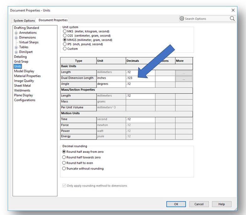
For your dimensioning standards, make sure you select the units (and how many decimals are displayed) for every model you create. We’ll always be starting out with a rough “paper sketch” in this class so you’ll be able to see the dimensions and visible decimals before you start modeling. Note that most of the models in the textbook are in millimeters. Always set the “Decimals” such that the most precise dimension in the rough sketch is displayed with all its decimal places. For example, if the most precise dimension on your rough sketch is 3.950 (3 decimal places of precision) set the decimals for Length to “.123” in the Document Properties – Units dialog box (Figure 2-12 and below):
LEARNING SKETCHER TERMS (page 2-14)
This is a pretty important section. The terms defined here are important for every modeler to know and understand.
ORIGIN (page 2-14)
We talked about the origin a little while back and here it is again. And note that it’s the first term defined.
The origin exists where the two red arrows meet. These arrows represent the vertical and horizontal directions of the current sketching plane. The origin is located at the (0,0) coordinate.
The origin itself should be denoted by a blue colored point/dot or a red star, but sometimes it is not visible. The visibility of the origin is controlled by the View Origins command in the Hide All Types command (I call it the “eyeball”) located in the View (Heads-Up) Toolbar.
INFERENCING LINES (page 2-15)
Read this section carefully. In a 2D CAD program like AutoCAD we use quite a few construction lines to make sure everything lines up properly. This can be a real pain. Luckily, Solidworks has what are called “inferencing lines”.
Inferencing lines are temporary lines that are used to track a particular point on the screen. They are only displayed when a sketching tool is active (ie. the LINE tool). They are dashed lines and automatically show up when you sketch. They are created from the endpoints (or the midpoint) of a sketched entity. See Figure 2-15 and below:
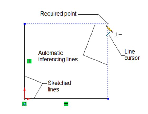
Figure 2-15 Inferencing Lines in Solidworks
We typically use these inferencing lines to located an intersection point between two imaginary lines that helps us properly line up entities as we sketch without having to create permanent construction lines.
Inferencing lines are either blue or yellow in color, depending upon whether relations are being applied.
SELECTING ENTITIES (page 2-15)
This section talks about the various methods of selecting entities when you are sketching:
- Select Tool
- Box Selection
- Cross Selection
- Lasso Selection (I don’t use this at all)
- SHIFT + CTRL Keys
Selecting works pretty much the same in Solidworks as it does in AutoCAD. Remember that a Sketch tool must be active for the selection methods to work.
Ignore the section titled Invert Selection Tool.
The next several sections cover the various sketching tools that are available in Solidworks. Again, most of these operate the same as the ones in AutoCAD so you should be able to master these pretty quickly. I’m not going to spend time in this guide going over these in detail because the book covers them extremely thoroughly. I will, however tell you which of the tool to look at and which ones you can skip over.
NOTE: Sketch editing tools (like trim, extended, rotate, etc) are not covered in this Chapter. They will be covered in Chapter 3.
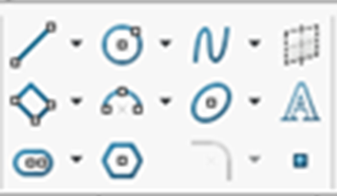
Next we cover some of the basic 2D sketching tools found in Solidworks. Fortunately, they are similar to the sketching tools found in AutoCAD. Their command icons are shown below. If you “hover” over a Sketch Tool command icon with the cursor, its name will be displayed.
DRAWING LINES (page 2-17)
This is about the LINE Tool. Read through all of this. We draw a lot of lines! Similar to AutoCAD, there are multiple orientations you can select when sketching a line:
- As Sketched (typically used)
- Horizontal
- Vertical
- Angle
Take a look at Drawing Tangent or Normal Arcs using the Line Tool on Page 2-21 through 2-22. It’s a pretty cool feature of Solidworks that you don’t see in AutoCAD. Also, be sure to look at Drawing Construction Lines (Centerlines) on Page 2-22.
DRAWING CIRCLES (page 2-23)
This is about the CIRCLE Tool. Read through all of this. We draw a lot of circles! As with AutoCAD, there are multiple ways to create a circle:
- Centerpoint + Radius (typically used)
- 3-Point
Note that you can also draw a construction circle (page 2-25).
DRAWING ARCS (page 2-25)
This is about the ARC Tool. Read through all of this. Just like in AutoCAD, drawing arcs can be a real problem. Arcs are pretty complex pieces of geometry and sometimes CAD systems find them hard to “solve”. As with AutoCAD, there are multiple ways to create an arc in Solidworks:
- Centerpoint (most commonly used)
- 3 Point
DRAWING RECTANGLES (page 2-29)
This is about the RECTANGLE Tool. Read through all of this as we draw a lot of rectangles. As with AutoCAD, there are multiple ways to create a rectangle in Solidworks:
- Corner (commonly used)
- Center + Corner (commonly used)
- At an Angle
How to draw parallelograms is also discussed, but we don’t create very many parallelograms so just skin this section.
DRAWING POLYGONS (page 2-32)
This is about the POLYGON Tool. We don’t create very many parallelograms so just skim this section.
DRAWING SPLINES (page 2-34)
This is about the SPLINE Tool. We don’t create splines this semester so just skim this section.
DRAWING SLOTS (page 2-35)
This is all about the SLOT Tool. Read through all of this. There is no tool in AutoCAD to draw slots, even though we draw quite a few of them. So, this tool is real timesaver if you have slot features to sketch. The SLOT tool can create straight slots and arc slots. There are multiple ways to sketch a slot, depending upon what information you know about the slot:
- Straight Slot
- Centerpoint Straight Slot
- 3-Point Arc Slot
- Centerpoint Arc Slot.
PLACING SKETCH POINTS (page 2-37)
This section is about the POINT Tool. We don’t place too many points in sketches this semester so just skim this section.
DRAWING ELLIPSES (page 2-37)
This section is about the ELLIPSE Tool. We don’t create many ellipses this semester so just skim this section.
DRAWING ELLIPTICAL ARCS (page 2-38)
The ELLIPSE Tool is used to create elliptical arcs. We don’t create many ellipses this semester so just skim this section.
DRAWING PARABOLIC CURVES (page 2-39)
The ELLIPSE Tool is used to create parabolic curves. We don’t create parabolas this semester so just skim this section.
DRAWING CONIC CURVES (page 2-40)
The ELLIPSE Tool is used to create conic curves. We don’t create conic curves this semester so just skim this section.
DRAWING DISPLAY TOOLS (page 2-41)
Well, we’re done with sketching tools for now. On to some information about drawing display tools!
Drawing display tools allow you to modify the display of your work by “zooming” or “panning”. AutoCAD and all CAD programs have drawing display tools similar to those found in Solidworks.
Note that there are specific command buttons you can click to invoke specific pan or zoom functions. They are talked about in the textbook and can be found in the View (Heads-Up) Toolbar. I pretty much just use my mouse to invoke pan and zoom “on the fly” as I work:
To Zoom: Roll your mouse’s wheel forward or backward to zoom in and out of your work.
To Pan: Click and hold down the CTRL Key and your mouse’s wheel. Move your mouse to pan the image.
To Rotate: When you are working remotely using CITRIX, you can rotate a model by simply pressing the mouse’s wheel and move your mouse. Note that we do not rotate sketches (but we do rotate solid models later in the class).
NOTE: If you are working from any on-campus computer workstation, you will need to use a Rotate command to rotate (using your mouse will not work). Watch the following YouTube for more information on how to add a Rotate command icon to your View (Heads-UP) Toolbar:
SHADED SKETCH CONTOURS (page 2-43)
This feature not used in this class.
DELETING SKETCHED ENTITIES (page 2-43)
You can easily delete any entity you’ve sketched by first selecting it and then clicking on the DELETE key. You can select a single entity or multiple entities to delete.
CONGRATULATIONS! You are done with Chapter 2!!
