1 Introduction to Solidworks 2019
CHAPTER 1 INTRODUCTION TO SOLIDWORKS 2019
This chapter provides a “50,000-foot overview” of Solidworks. It gets into some level of detail, but note that we’ll see most of this material again in later chapters. So, try to not get too bogged down here.
Read over the following introductory PowerPoint: Introduction to Solidworks and Solid Modeling
It is important to note that Solidworks is a “native Windows” program – it was the first of its type to be designed from its inception to actually run on Windows. Therefore, it has a Windows-based graphical interface and takes advantage of many of the built-in Windows features we are all familiar with: like “drag-and-drop”, cut-and-paste. This makes Solidworks pretty easy to learn and use. There’s a later assignment to read an introductory PowerPoint about Solidworks & Parametric Modeling – be sure to complete it.
There are many add-ins to Solidworks that are used for specific design tasks. These include Motion, Simulation, Routing, Plastics, CircuitWorks, and more. We don’t have enough time this semester to get into these add-ins, but you might encounter them during your career. What’s important this semester is to gain a working knowledge of the basic tools in Solidworks. You can always learn more of the capabilities – like the add-ins – at a later time as needed.
Solidworks uses a “PARAMETRIC” approach to modeling. This is different that a standard 2D CAD program like AutoCAD. When you use Solidworks, you capture the design intent by using features and constraints – a rich database of digital information is created about the part in the background. A standard 2D CAD system uses a “direct modeling” approach in which “dumb” geometry is created. Because a parametric modeling program captures design data as the model is created, the model itself can be used for purposes other than just creating drawings. For example, the model can be used to:
(1) generate codes for computer numerical control machine tools,
(2) create molds and simulate material flow for plastic injection molding,
(3) create files to drive 3D printers,
(4) run engineering analyses (like finite element analysis), and more.
And of course, they can be used to create good old-fashioned engineering drawings as well. Parametric modeling is superior to direct modeling when you are working on highly complex parts, families of parts with slight variations, parts that require frequent updating, etc. It is interesting to note that when we “sketch” in Solidworks, we employ many of the same tools and techniques that we use in AutoCAD! So, don’t forget all those skills you learned in the AutoCAD class – you’ll need them later on this semester! There are assignments about Parametric Modeling – be sure to complete them.
Unlike AutoCAD, Solidworks has three basic “MODES” that we employ while modeling: PART, ASSEMBLY and DRAWING. Most parametric modeling programs, like Inventor for example, have similar modes. They are described briefly in this chapter, but we use them extensively in later chapters. This course focuses on building competency in using these three modes.
Below are the icons you’ll see in Solidworks for the 3 modes:
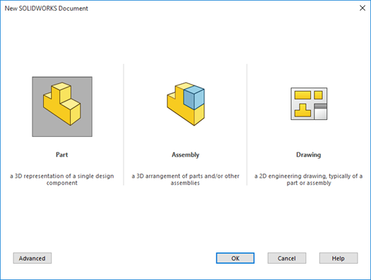
Part Mode (page 1-2)
Quite simply put, PART mode is where we create our part models. You can’t create assemblies or drawings unless you first have some parts, so this is where we will start our work this semester.
PART mode is feature-based parametric environment used to create “solid models” of parts. We start out by “sketching” entities on a drawing plane (typically one of the three default principle planes in Solidworks – front, top or right side. Dimensions are added as are relations to capture the “design intent”. The sketching tools we use to create sketch entities are very similar to the sketching tools found in 2D CAD programs like AutoCAD.
Once the sketch is created, it can be converted into “base features” by two primary methods:
- extruding the sketch into a solid extruded feature, or
- revolving the sketch.
A material can be assigned to a solid model once it has been created. When you assign a material, its engineering properties (density, Young’s Modulus, tensile strength, etc.) are immediately applied to the model. This allows us to analyze the part’s mass, volume, surface area, center of gravity, moment of inertia, etc.
We start using the PART mode in Chapter 2 and get into applying material in Chapter 5.
Assembly Mode Mode (page 1-3)
In the ASSEMBLY mode you can combine together components to create an assembly. Parts are “assembled” together using Solidworks’ MATE tools. Just as during physical assembly of parts on the production floor, the various MATES applied in the digital environment constrain the various parts by eliminating degrees-of-freedom.
We start using the ASSEMBLY mode in Chapter 12.
Drawing Mode (page 1-3)
The DRAWING mode is used to create ANSI (or ISO) compliant engineering documentation for a part and/or assembly. This documentation is typically in the form of drawing views (similar to those created in 2D CAD). These include orthographic views and isometric views.
Parametric dimensions applied in the PART mode can be automatically used to create the associated drawing dimensions. Other annotations (ie., surface finishes, notes, etc.) can be applied to the drawing views as needed. Bills of Material (BOMs) and balloons can be automatically generated and applied to assembly drawings.
We start using the DRAWING mode in Chapter 14.
SYSTEM REQUIREMENTS (page 1-4)
You do not need to concern yourself with this section unless you intend to download and install a copy of Solidworks to your PC. For this class, you will access the software via the College’s network using CITRIX and you will not need to install any software. Note that it takes a pretty powerful computer to smoothly run these parametric modeling programs. Luckily, that is not an issue for us. Just about any Windows-based PC you use to connect to the internet will work for our class.
GETTING STARTED WITH SOLIDWORKS (page 1-4)
This section starts out assuming that you are installing a stand-alone version of Solidworks on your computer. Of course, that’s not how we do it at the College. We have the software loaded on the College’s network which you access directly, whether you are working on a College computer on campus or remotely from home.
We’ll get into starting a new part when we get to Chapter 2. For now, just read over the process on pages 1-5 through 1-7.
Do pay particular attention to the Units and Dimension Standard dialog box, Figure 1-4 on page 1-6. This box will come up the first time you access Solidworks. This gives you the opportunity to set your default selections for Units and Dimensioning Standard.
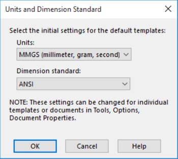
Don’t just select the defaults displayed. It is important that you set your Units to IPS (inches, pounds, seconds) and your Dimension Standard to ANSI. You can change these selections at any time (and you’ll have to for units based on the part you are creating) – we’ll discuss this later in the course.
Remember that here in the USA we use the ANSI dimensioning standard no matter what units we are applying to our part (inches versus millimeters, for example).
Also, study Figure 1-5 on page 1-7. This figure shows the key elements of the Solidworks user interface. This can also be found in the Chapter 1 PowerPoint.
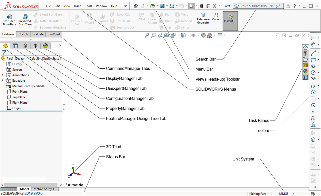
I try to use all the “standard” names for everything in the user interface, but like everyone else I’m not always perfect. It is important, however for everyone to have a good working knowledge of these terms. Do your best to memorize them.
MENU BAR AND SOLIDWORKS MENUS (page 1-7)
In Solidworks, like AutoCAD and Microsoft Word, the display area of the screen is maximized by grouping the tools that have similar functions or purposes.
You can invoke a command from one of 4 places in Solidworks:
- The Solidworks Menus
- A CommandManager
- A specific Toolbar, or
- A shortcut menu (by right-clicking)
The SOLIDWORKS MENUs are located in the top left-hand corner of the screen above the drawing area. These are drop-down menus that we sometimes use. Note that the menu selections may not be visible at first. When you move the cursor to the arrow on the right-hand side of the Solidworks logo the menu selections will appear. If you want them to stay visible, all you have to do is push the push-pin button on the right-hand side of the menu bar. I recommend you do this. The Solidworks Menus are the comprehensive repository for all the available tools in Solidworks.

COMMANDMANAGER (page 1-8)
Invoking a tool from a CommandManager is the most convenient method. CommandManagers in Solidworks are essentially equivalent to Ribbon Panels in AutoCAD. The CommandManagers are docked above the drawing area. An example CommandManager (for sketching) is shown in Figure 1-8 on Page 1-8 and below:
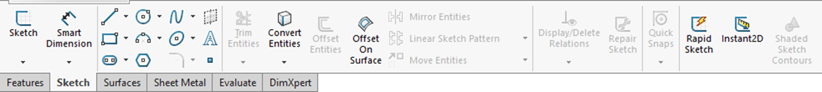
Note that there are different CommandManager configurations for different design environments. Figure 1-8 (page 1-8 and above) is the Command Manager for the SKETCH environment. Note the presence of all the sketch tools. If we click on FEATURES, we’d get a Command Manager with a completely different set of tools (Figure 1-9 on Page 1-8 and below):
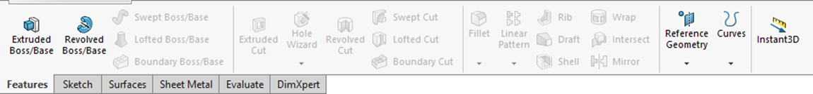
We predominately use the SKETCH and FEATURES CommandManagers in this class. You can look over the various other CommandManagers for DimXpert, Sheet Metal, Mold, etc. on pages 1-8 through 1-10 if you want, but we won’t be using them.
Customized COMMANDMANAGER (page 1-11)
We don’t customize CommandManagers in this class. You can look this section over if you like.
TOOLBAR (page 1-12)
This section covers the various toolbars that we have available to use in Solidworks. Remember, we use the CommandManager as the primary vehicle to invoke commands, but sometimes a toolbar is easier.
Pop-Up Toolbar (page 1-12)
Solidworks is “right-click” sensitive. If you click the right mouse button on your mouse, a context-sensitive pop-up toolbar with appear on your screen. It will contain the command icons that Solidworks associates with what you were doing at the time you right-clicked – a list of suggestions in other words. This capability comes in handy when you aren’t quite sure what command you want to use. Figure 1-22 on Page 12 and below depicts an example of a pop-up toolbar invoked by right-clicking your mouse:
Each icon in a toolbar is a specific tool. If you hover your mouse over one of the tool icons, its name will be displayed.
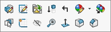
View (Heads-Up) Toolbar (page 1-12)
Figure 1-22 on Page 1-12 and below depicts the View (Heads Up) toolbar. Think of it like the heads-up display used in fighter jets which permits the pilot to keep his eye on the target rather than looking down at a dashboard. This toolbar is unique as it is always visible on the Solidworks interface. It contains many of the most commonly-used display tools, including ZOOM.

Note that all of the tools located in the View (Heads Up) toolbar are also available from the Solidworks Menus.
Shortcut Bar (page 1-13)
Not used in this class.
Mouse Gestures (page 1-13)
Not used in this class.
DIMENSIONING STANDARDS AND UNITS (page 1-14)
Because Solidworks is a product of Dassault Systems, which is based in Europe, it is delivered such that “out-of-the-box” it typically installs using the ISO dimensioning standard and millimeter-based units.
Because Solidworks is used all over the world, it has various built-in dimensioning standards that can be used. These include ANSI, ISO, JIS, DIN, etc. Because we live and work in the good old USA, we always use the ANSI dimensioning standard (unless another standard is specified by our customer). This will ensure our dimensioning on drawings follows the established ANSI standard and our drawing views are displayed in third-angle projection. Again, we’ll talk more about this as we start modeling in Chapter 2.
There are lots of units available for use in Solidworks. Our textbook uses millimeters as its default units. That’s okay. Although our author recommends we set our dimensioning standard to ISO, we just go ahead and use the ANSI dimensioning standard with any millimeter units we may use (yes, you can do that!). See my notes about this on the top of page 4 of this guide. Remember that we can set the dimensioning standard at any time by using the Options command icon in the Solidworks Menu. Again, we’ll talk more about this as we start modeling in Chapter 2.
IMPORTANT TERMS AND THEIR DEFINITIONS (page 1-14)
Make sure you read these term over and make an attempt to understand their importance to the overall modeling process. Again, they are just introduced here and we’ll be using this stuff as we begin modeling in Chapter 2 and beyond.
Feature-Based Modeling (page 1-14)
A feature is the smallest building block of a part that can be modified individually. Part models are created in Solidworks by combining features until the final solid part is created. Examples of features include things like 3D fillets, 3D rounds, holes, slots, etc. We don’t have features in traditional 2D CAD. If properly implemented, these features should reflect the design intent of the part and will automatically adjust their values to changes in the model. There will be more on the concept of design intent in some of your upcoming assignments.
Parametric Modeling (page 1-14)
Parametric modeling uses the standard properties or parameters to define the shape and size of a geometry. This allows us to change the size or shape of a selected geometry without considering its original dimensions. These changes can be done at any time in the design process. See Figures 1-24 and 1-25 on page 1-15 to view an example of how easy it is to change the number and size of all the hole features on the Pipe Housing.
Read this supplement to learn more about how parametric modeling works: BASICS OF SOLID MODELING
Watch these YouTube videos to learn more about parametric modeling:
Bidirectional Associativity (page 1-15)
This is a powerful capability of Solidworks. The is bidirectional associativity between the 3 modes of Solidworks – PART, ASSEMBLY, and DRAWING. What does this mean?? After you create a solid model in the PART mode, you can “borrow” it to put into an assembly in the ASSEMBLY mode or to create the necessary drawing views in the DRAWING mode. That in-and-of-itself is pretty cool, but it goes beyond that. If you create a drawing view from a part and then go back and make a design change to the original part you “borrowed”, the drawing view will also change! Same thing happens if the part was placed into an assembly. Just think about how much time this would save when you make a design modification to a part! Of course, this can also be dangerous if you don’t control the changes properly. See Figures 1-26 and 1-27 on pages 1-15 and 1-16 to see how a drawing changes when the original part model was changed.
SWIFT Technology (page 1-16)
We don’t really use “XPERTS” in this class. They are discussed in future chapters.
Geometric Relations (page 1-16)
Geometric relations are used to apply a relationship between selected sketch entities, planes, axes, edges or vertices. Available geometric relations include: tangent, perpendicular, coincident, concentric, horizontal, vertical, etc. These are defined in more detail on page 1-17 thru 1-18.
Automatic Relations (page 1-17)
Geometric relations are automatically added to your sketches as you create entities. For example, if you draw a horizontal line, Solidworks will automatically apply a “horizontal” relation to that line and the line will act like a horizontal line so long as the relation is applied to it. If you draw a line such that it touches the edge of circle, Solidworks will automatically apply a “tangent” relation that that situation.
When a geometric relation is applied, Solidworks displays a symbol indicating that relation. Each geometric relation has its own unique symbol.
This all can be a bit difficult to comprehend at first, but as time goes by you’ll be able to easily identify what the most commonly used symbols represent and what that means to your sketch. Our book doesn’t include a list of the various symbols, so I’ll do that with a supplemental document when the time is right.
For now, you can visit this website to see a good listing of the symbols: https://www.javelin-tech.com/blog/2014/01/solidworks-sketch-relations-summary/.
Sometimes Solidworks doesn’t apply the relation you want (or it adds one you don’t want). So yes, you can also add (and delete) relations manually to your sketch.
We’ll talk a lot more about geometric relations as we start sketching in Chapter 2.
Just read over these sections:
Blocks (page 1-18)
Library Feature (page 1-18)
Design Table (page 1-18)
Equations (page 1-18)
Collision Detection (page 1-19)
What’s Wrong Functionality (page 1-19)
SimulationXpress (page 1-19)
Physical Dynamics (page 1-19)
Physical Simulation (page 1-20)
Seed Feature (page 1-20)
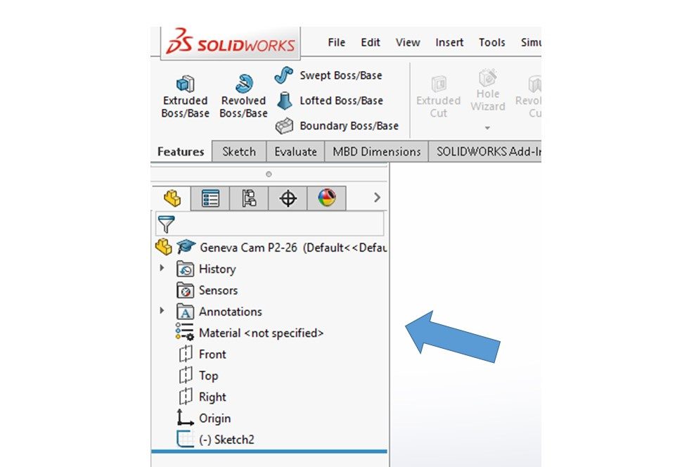
FeatureManager Design Tree (page 1-20)
The FeatureManager Design Tree is one of the most important components of Solidworks (see below). It is displayed to the left of the drawing area and contains real-time information about your model as you build it. You can easily select and edit the sketches and features you have created in your model by selecting them from the FeatureManager Design Tree. We’ll really be using the FeatureManager Design Tree when we start sketching in Chapter 2.
Just read over these sections:
Absorbed Features (page 1-20)
Child Features (page 1-20)
Dependent Features (page 1-20)
AUTO-BACK-UP OPTION (page 1-20)
Solidworks automatically creates a saved copy of the document you are working on at regular intervals. This helps to avoid loss of work should you encounter some sort of system crash. Make sure this capability is turned on when we start in Chapter 2 (see how to do that on the bottom of page 1-20).
Although we can let the system do automatic saves for us, I strongly recommend that you get into the habit of regularly doing a manual save as you work along or after completing something really complicated that you wouldn’t want to have to do again. Believe me, crashes happen at the worst possible times and the loss of data between auto-saves can be significant – especially if you are a fast modeler.
Note: Always make sure you know where your saved files are being saved! I recommend doing a FILE-SAVE AS right after starting a new document so that the system knows where you want the file saved. Don’t just hit the SAVE button as that will save your file to a default system location that you may not be able to find later. Once you do that FILE-SAVE AS once, the auto-save functionality knows where you want your file saved to.
SELECTING HIDDEN ENTITIES (page 1-21)
Just read this section over.
HOT KEYS (Page 1-21)
We don’t use Hot Keys in this course.
COLOR SCHEME (page 1-23)
I just use the color scheme that gets loaded by default by Solidworks. I recommend you do the same.
