8 Advanced Modeling Tools – II
CHAPTER 8 ADVANCED MODELING TOOLS II
This chapter builds on what we learned in Chapter 7. It provides some additional advanced modeling tools that help us to capture the design intent of the part. These tools include:
- Mirror,
- Linear patterns,
- Circular patterns,
- Ribs,
- Displaying section views of models in real-time,
- Changing the display state of a part model
CREATING MIRROR FEATURES (page 8-2)
The Mirror tool at the (Feature-based modeling level works about the same as it did in sketch mode. But here you can mirror features – very powerful, indeed! Mirror saves modeling time and also can be used to embed design intent into your model! In addition, it improves the accuracy of your model by ensuring that all features that should be the same are, in fact, exactly the same.
The Mirror tool creates a copy of the features you select to be mirrored. This allows you to only have to model a feature once when there are multiple instances, thus supporting the old 3D modeling adage: “we create a feature once no matter how many times it is used in the model”.
The features to be copied are “mirrored” about a mirror plane which we must specify. This can be a default plane (Top, Front, Right), a reference plane (see Chapter 6), or a planar face on the model. Remember that when we used the Mirror Entities tool while sketching in Chapter 3, we mirrored the sketch entities about a centerline. So, same basic idea here.
In our system, the Mirror tool icon should be available on the Features CommandManager (see below). If so, you can select it directly to invoke the Mirror tool.
If you don’t see the Mirror tool icon, you can invoke the Mirror tool by first selecting the Linear Pattern command button from the Features CommandManager. Then select Mirror from the list of tools (see Figure 8-1), Page 8-2 and below).
The Mirror PropertyManager will be displayed. (See Figure 8-2, Page 8-2 and below). Note that the Mirror Face/Plane rollout is highlighted (in blue) – its asking you to select the face or plane that you want to mirror feature around. You can select it directly from the model itself or from the Design Tree visible in the drawing area (see figure to right).
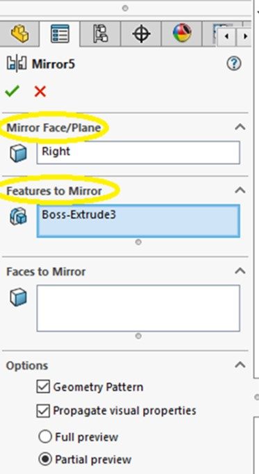
Next, you will need to select the feature(s) you wish to mirror using the Features to Mirror rollout. Again, you can select it directly from the model itself or from the Design Tree visible in the drawing area.
Keep the default settings for everything else in the PropertyManager.
MIRRORING WITH AND WITHOUT THE GEOMETRIC PATTERN (page 8-2)
We always use the default situation which is the Geometric Pattern check box is cleared out. Therefore, mirrored features will have the same relationships applied as for the original.
PROPAGATING VISUAL PROPERTIES WHILE MIRRORING (page 8-4)
We always use the default situation which is the Propagate Visual Properties box is checked. Therefore, mirrored features will have the same visual properties as those assigned to the original.
MIRRORING FACES (page 8-4)
We don’t really use this capability this semester. We just mirror features. Just read over.
MIRRORING BODIES (page 8-5)
We don’t really use this capability this semester. We just mirror features. Just read over.
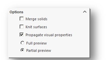
OPTIONS ROLLOUT (page 8-6)
Make sure that the Merge Solids checkbox in the Options rollout is always checked. This will merge the mirrored feature with the original and turn into a single body.
CREATING LINEAR PATTERN FEATURES (page 8-6)
Being able to create a “pattern” of multiple copies of a feature is another way to help us obey the old adage “we create a feature once no matter how many times it is used in the model”.
Most CAD programs have some sort of patterning tool to automate the drawing of multiple copies of an existing entity in a pattern – whether a linear (straight line) pattern or a circular pattern. Although you can do this manually, it can be extremely tedious and error prone to have to recreate all the features of a complex part multiple times. The copies created are exact copies of the original entity.
The Linear Pattern tool is the Feature-based cousin of the sketch-based Linear Sketch Pattern tool discussed in Chapter 3 (see Page 3-22). In reality, we seldom create linear sketch patterns in the 2D sketch. Like fillets and chamfers, we almost always create patterns as 3D features.
Most linear patterns are created as FEATURES and that’s how you should do them form this point forward.
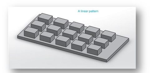
The Linear Sketch Pattern tool for features is used to create one- and two-dimensional rectangular patterns of a solid feature.
Like the Fillet and Chamfer tools which share a command icon, if the down arrow on the bottom of the Linear Pattern Command icon on the Features CommandManager is clicked, it reveals the Circular Pattern tool. This aspect of the tool is covered in the next section of this guide.
Like the 2D version of this tool, you need to select the feature(s) you want to create the pattern from using the Features and Faces rollout box in the Linear Pattern PropertyManager. You can select it/them directly from the model itself or from the Design Tree visible in the drawing area
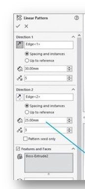
In addition, you need to supply an indicator of the direction(s) you want the pattern to be created along. This is done by clicking on a reference line or surface while in the Direction 1 rollout. You would need to also do this for a second direction (Direction 2 rollout) if you were creating a 2D pattern.
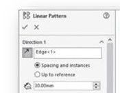
You also need to define the spacing between each instance of the feature in the pattern. This entry is made in the Spacing spinner in the Direction 1 rollout. Again, if this is a 2D pattern you would need to define the spacing in each direction of the pattern. The Direction 2 rollout would be used for the second direction. The two directions do not have to have the same spacing.
NOTE: The spacing between the features in a direction are always equal – you can’t use this tool to create a pattern in which the features in a direction have different spacings!
The number of instances in each direction needs to be defined as well via the Instances spinner in the Direction 1 rollout. Again, if this is a 2D pattern you would need to define instances in each direction of the pattern. The Direction 2 rollout would be used for the second direction. The two directions do not have to have the same number of instances.
As you create the pattern, a preview in yellow will be displayed so you can confirm that the pattern is being created the way you envisioned it.
Patterns can be a bit tricky to create correctly, so be patient.
INSTANCES TO SKIP (page 8-9)
Just read over. Probably will not use this semester.
INSTANCES TO VARY (page 8-10)
Just read over. Probably will not use this semester.
CREATING PATTERN USING A VARYING SKETCH (page 8-11)
Skip this section.
PROPAGATING VISUAL PROPERTIES WHILE PATTERNING COMPONENTS (page 8-12)
Same as discussed for Mirror command. Just leave the default conditions.
CREATING CIRCULAR PATTERN FEATURES (page 8-12)
Watch the YouTube video below covering the basics of creating circular feature patterns in Solidworks:
The Circular Pattern tool is the brother of the Linear Sketch Pattern tool we talked about in Chapter 3. Like the Linear Pattern tool, it is feature (3D) based not sketch (2D) based. This tool creates circular patterns of selected features.
Most circular patterns are created as FEATURES and that’s how you should do them form this point forward.
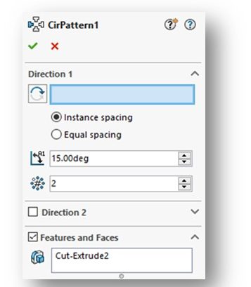
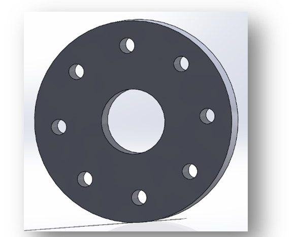
This tool is used frequently in practice as many mechanical parts have bolts laid out in a circular pattern. This arrangement is common on pipe flanges. See example at right.
If the down arrow on the bottom of the Linear Pattern tool is clicked, it reveals the Circular Pattern tool. This aspect of the tool was covered in the previous section.
This tool works similarly to the Linear Pattern tool discussed in the previous section, except that the pattern is in a circle or along an arc (partial circle). The features that are patterned are always equally spaced apart. Remember that you must have the features you wish to pattern already created before starting this tool.
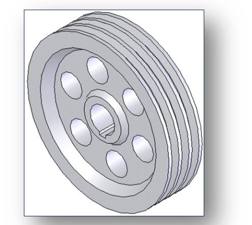
You create a circular pattern using the Circular Pattern PropertyManager (see Figure 8-27, Page 8-12 and below).
The Features and Faces rollout will be activated, but you can start out anywhere you wish. I normally set the direction of the pattern first using the Direction 1 rollout, similar to what we did in a linear pattern. This can be a bit tricky however for circular patterns. If you don’t have a circular feature (like the edge of the flange disk – see below) to use, it gets more complicated in a hurry – and more than we can cover in this study guide.
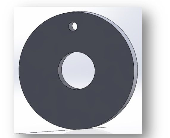
You then need to select the feature you wish to pattern using the Features and Faces rollout. you can select it directly from the model itself or from the Design Tree visible in the drawing area. Be sure you actually select the feature. Then indicate the number of instances using the Instances spinner.
We typically keep the features in the pattern equally spaced and spread them over a complete circle (360 degrees), but that depends on the specific design. You can use the options in the Direction 1 rollout to change these, if needed.
The resulting 8-hole circular pattern is shown below:
Here’s a good tutorial showing how to model a fairly complex disk brake rotor using many of the modeling tools from Chapter 8 (and before), including a circular pattern of hole features:
CREATING CIRCULAR PATTERN USING A DIMENSIONAL REFERENCE (page 8-13)
Just read over. Probably will not use this semester.
CREATING SKETCH DRIVEN PATTERNS (page 8-14)
Just read over. Probably will not use this semester.
CREATING CURVE DRIVEN PATTERNS (page 8-16)
Just read over. Probably will not use this semester.
CREATING TABLE DRIVEN PATTERNS (page 8-18)
Just read over. Probably will not use this semester.
CREATING FILL PATTERNS (page 8-20)
Just read over. Probably will not use this semester.
CREATING VARIABLE PATTERNS (page 8-24)
Just read over. Probably will not use this semester.
CREATING RIB FEATURES (page 8-25)
This is a unique and handy capability of Solidworks. Although we don’t create a ton of rib features this semester, ribs are very common in mechanical parts. Ribs are thin-walled structures that are used to strengthen a mechanical structure. The tools to create ribs in Solidworks are pretty easy to apply. Look this section over.
Ribs are created using the Rib tool. The command icon is located in the Features CommandManager.
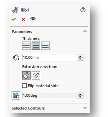
Clicking on the Rib command icon will open the Rib PropertyManager (see Figure 8-64, Page 8-25 and below).
You will be prompted to select a plane, a planar face, or an edge upon which to create the sketch that will be used to create the rib feature. Once the sketch is complete, you will need to close the sketch and go back to the Rib command to finish the rib. An existing sketch can also be used to create the rib.
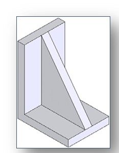
The sketches used to create the rib feature are single line sketches (see Figure 8-65, Page 8-26 and below). We don’t use the Extruded Boss/Base command to create the rib. The 3D aspects of the rib are created right in the Rib PropertyManager. Most importantly, this includes the thickness of the rib, which is set in the Parameters rollout.
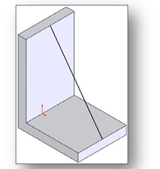
Watch the following instructor video showing how to create the rib feature shown in Figure 8-65 on Page 8-25:
DISPLAYING THE SECTION VIEW OF A MODEL (page 8-30)
We all know about the section views we create on paper drawings. When we are modeling, there are times when it would be helpful to create a temporary section view so we can look inside the part we are creating.
The Section View tool is used to display the inside of a part model by cutting it using a plane or face. The Section View command icon can be found on the View (Heads-Up) toolbar located at the top-center of your drawing area.

Clicking on the Section View command icon opens the Section View PropertyManager (Figure 8-79, Page 8-31 and below):
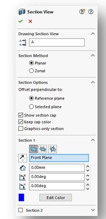
Using the Section View tool is pretty easy once you get the hang of it. In this class, you may not use it at all. Its an “in process” tool – you use it when you need it. You won’t mess up your model by using this tool as it is only affecting the view. Read this section over and familiarize yourself with this tool and use it when you need to.
CHANGING THE DISPLAY STATES (page 8-33)
In Solidworks, you can control the transparency of individual features and display your model in different display states.
While it might be appropriate to sometimes change the transparency or color of a feature on a model, we probably will not be doing that this semester.
We don’t really use this capability until we get to assemblies where an exploded view, when created, is actually a second state of your assembled model. When you want to create an exploded view drawing, you need to pull in the exploded view state.
We also sometimes use this capability in assemblies when we make a part on the assembly transparent or a certain color. This helps to add clarity to an assembly model. We’ll see this in Chapter 12.
Read this section over and be sure you at least understand what is happening here. You will need to reference back to this when we get to exploded view drawings in Chapter 15.
CONGRATULATIONS! YOU ARE DONE WITH CHAPTER 8!
