15 Working with Drawing Views – II
CHAPTER 15 WORKING WITH DRAWING VIEWS – II
This chapter builds on the work in Chapter 14 on the third and final “mode” of Solidworks – DRAWINGS.
In this chapter, we’ll first learn how to add and edit “annotations” to our drawings. Annotations include dimensions, notes, cosmetic threads, datums, datum targets, geometric tolerances, surface finish symbols, and weld symbols. We don’t have anywhere near enough time to cover all those, so we’ll focus on adding the two most common annotations – dimensions and notes – to our drawings. [It is assumed that everyone in this class already has a basic understanding ANSI dimensioning standards so we won’t be tracking back over that again. I have, however attached below the governing ANSI/ASME specification for dimensioning in case you’ve forgotten the basics of dimensioning: ANSI/ASME Y14.5M Dimensioning and Tolerancing
In addition, here are a couple of PowerPoints that summarize how to dimension various features (holes, cylinders, etc.):
We’ll also learn how to add centermarks, centerlines and hole call-outs to our drawings.
Next we’ll see how we can complete our assembly drawings by adding bills of material (BOMs) and assembly balloons.
We will also see how to edit our sheet format. This will allow us to edit the information in the title block.
So there’s plenty to cover in this chapter, but we won’t cover it all. Take note of the sections you should be reading closely and those you can either skip over or just browse through.
Re-watch the drawings video below to refresh your memory about how to work with drawings in Solidworks:
ADDING ANNOTATIONS TO DRAWING VIEWS (page 15-2)
Annotations are added after we generate the drawing views. Remember that drawing views are just “borrowed” from the part models we created first. Two types of annotations can be added:
- Generative – these are added while the part is being created in the Part mode (ie., dimensions on the sketch)
- Manual – these are added at the drawing level in the Drawing mode
We don’t really use generative annotations in this class, although we certainly could. Instead, we apply “manual” annotations, such as dimensions, at the drawing level. Of course, those dimensions are based on the dimensions we previously added at the part level anyway. As we learned in Chapter 14, Solidworks employs “bidirectional associativity”. This means that dimensions added to a model while in the Part mode are automatically carried forward into any assembly or drawing that model is used in.
GENERATING ANNOTATIONS USING THE MODEL ITEMS TOOL (page 15-2)
This section is used if we employ generative annotations (directly added to the drawing from the part model). You can read this over, but we will not be using this approach in this class.
One of the issues with the Model Items tool described in this section is that the dimensions are imported onto the drawing in a “haphazard” fashion. Time and effort must be expended to adjust the position the imported dimension so that the drawing meets ANSI dimensioning standards. It can be a considerable effort to untangle the imported dimensions. Plus, anything that we can bring in using the Model Items tool described in this section can also be added manually.
ADDING REFERENCE ANNOTATIONS (page 15-4)
This section discusses how to add annotations (dimensions, notes, cosmetic threads, datums, datum targets, geometric tolerances, surface finish symbols, and weld symbols) to drawing views using a manual approach.
More details on these are included in subsequent sections of this chapter.
ADDING REFERENCE DIMENSIONS (page 15-4)
Drawing dimensions have their own unique set of drafting standards associated with them that designers should understand. These standards are embodied in ASME Y14.5 Dimensioning & Tolerancing.
As stated, in this chapter we’re going to be working with the dimensioning tools in Solidworks. Solidworks has ANSI Inch, ANSI Metric and ISO dimensioning systems capability. We use the ANSI drafting standard here in the USA and can apply both inch and metric dimensions.
This section discusses how to add dimensions to drawing views using a manual approach. Don’t confuse the “reference dimension” term the author uses here with “reference dimensions” used in the ANSI drafting standards. The dimensions you place into your drawing views using this method are dimensions – period – and can be used to govern the fabrication/assembly of the design.
You can use the Smart Dimension tool to add dimensions to your drawing views. The process is very similar to that used to add dimensions to sketches in Part mode. The Smart Dimension tool is located by selecting the Annotation tab and then clicking on the Smart Dimension icon located in the Annotation CommandManager (see figure below):
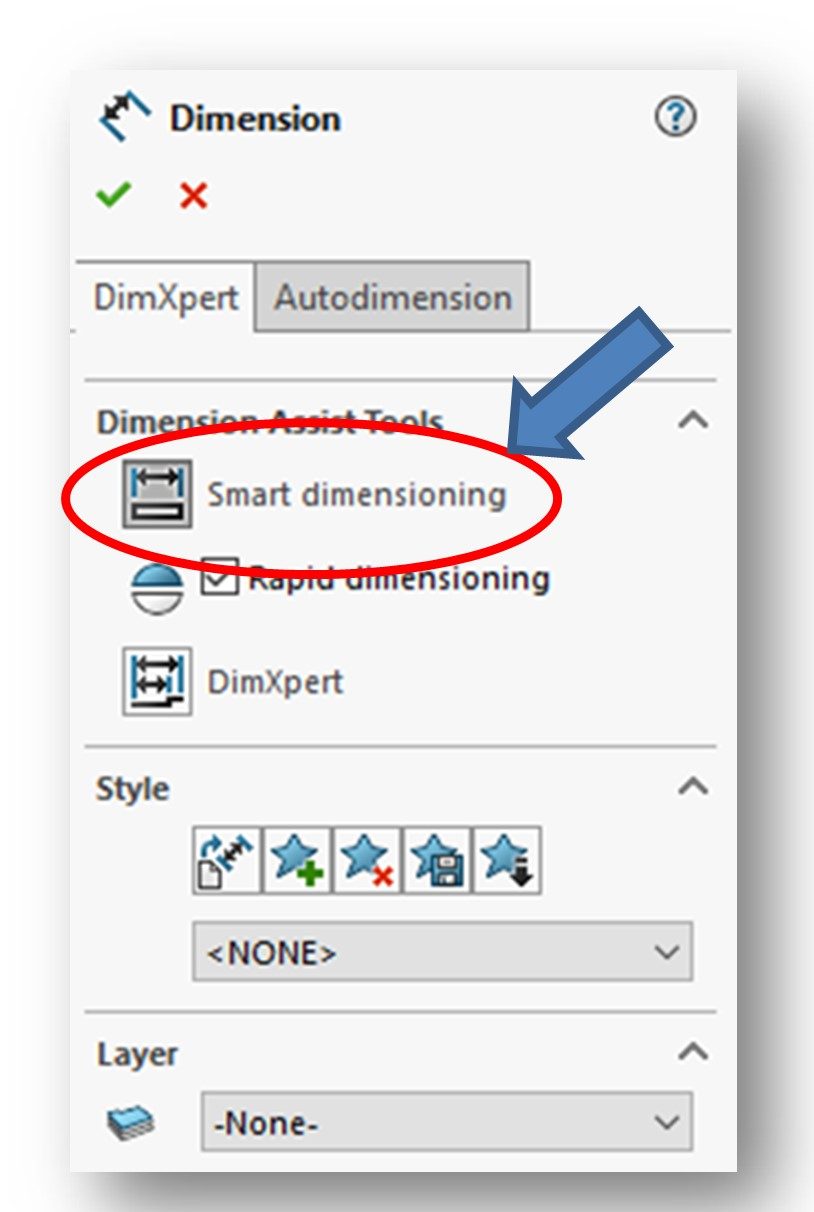
The Dimensioning PropertyManager will be displayed (see Figure 15-2, Page 15-5 and below). Note that by default the Smart Dimensioning option is selected in the Dimension Assist Tools roll-out.
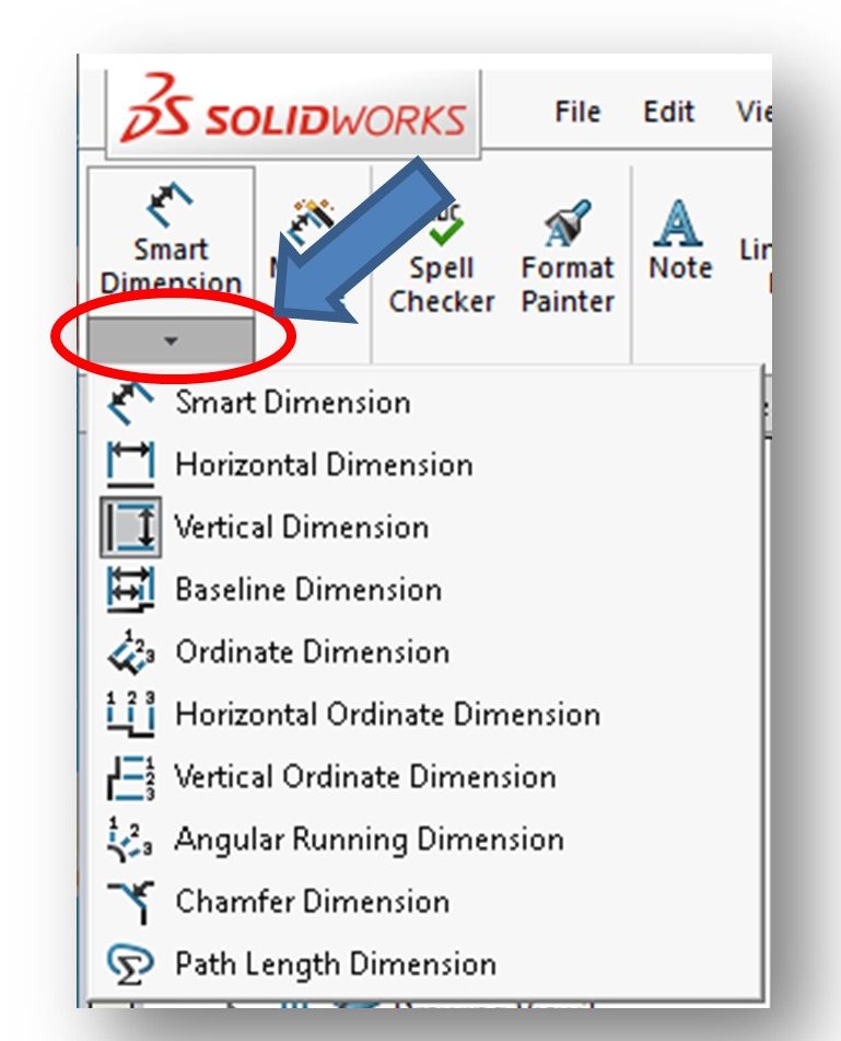
Alternatively, note that if you click the down-arrow below the Smart Dimension icon located in the Annotation CommandManager, you will be presented with a listing of Smart Dimensioning tools (vertical, horizontal, etc.) (see figure below):
Note that when you pass your cursor over a drawing view the dimensioning symbol is attached to your cursor (it looks like a ruler or caliper). You can go ahead and add dimensions to your drawing views similar to how you did while in the part model itself.
NOTE: We do not use the Autodimension Tool in this class. We manually add all of our dimensions.
ADDING CHAMFER DIMENSIONS (page 15-5)
The Chamfer Dimension Tool is used to add dimensions to a chamfer. It is located in the Smart Dimension fly-out menu. Read this section over and reference it if you need to dimension a chamfer.
There are multiple ways to develop and dimension chamfers. Chamfers were covered back in Chapter 7 (Advanced Modeling Tools – I).
ADDING NOTES TO THE DRAWING (page 15-6)
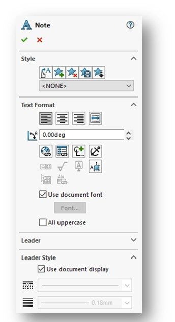
Notes can be added to drawings. One of the most common notes is a material call-out. To add a note, choose the Note button from the Annotation CommandManager. The Note PropertyManager will be displayed (Figure 15-5, Page 15-6 and below):
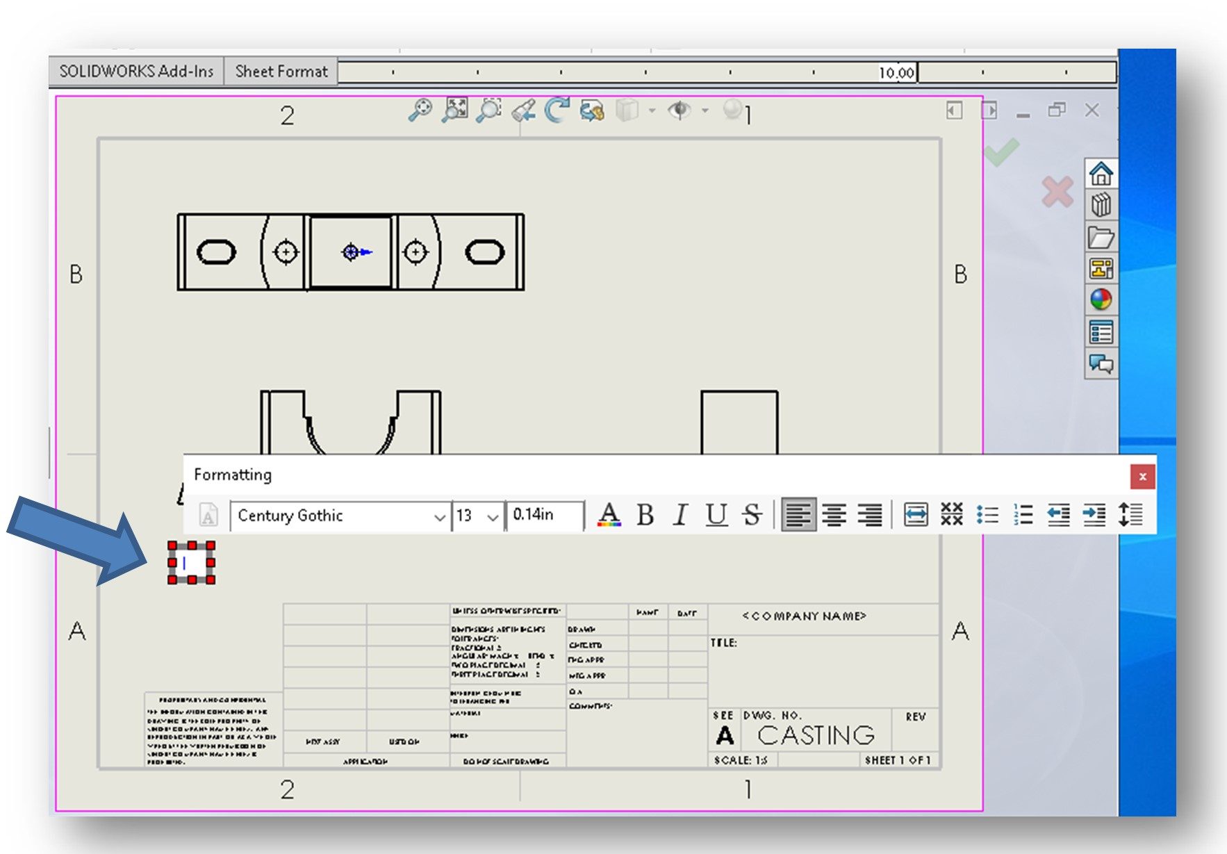
On invoking the Note PropertyManager, a rectangular box will be attached to your cursor. Move your cursor and place the box in the location where you want the text to appear and left-click. A text entry box will appear as will a Formatting toolbar (see figure below). The Formatting toolbar operates similar to the formatting tools you find in Microsoft Word.
Once you place a note on a drawing, you can relocate and/or edit it later.
ADDING SURFACE FINISH SYMBOLS TO THE DRAWING VIEWS (age 15-7)
Just read over. We don’t add surface finish symbols to drawings on this class.
ADDING A DATUM FEATURE SYMBOL TO THE DRAWING VIEWS (page 15-8)
Just read over. We don’t add datum feature symbols to drawings on this class.
ADDING A GEOMETRIC TOLERANCE TO THE DRAWING VIEWS (page 15-9)
Just read over. We don’t add geometric tolerances to drawings on this class.
ADDING DATUM TARGET SYMBOLS TO THE DRAWING VIEWS (page 15-12)
Just read over. We don’t add datum target symbols to drawings on this class.
ADDING CENTER MARKS TO THE DRAWING VIEWS (page 15-13)
Center marks are applied to circular entities, including circles and large arcs. As discussed in Chapter 14 (Working with Drawings – I), center marks are automatically applied when you create drawing views. Sometimes, center marks are not automatically generated or are not exactly the way you want them to appear. This often happens with slots and arcs. If for some reason center marks are not automatically generated, you can add them manually in the drawing view by using the Center Mark Tool.
Start out by selecting the Center Mark button from the Annotation CommandManager. The Center Mark PropertyManager will be displayed (See Figure 15-13, Page 15-13 and below). Also, your cursor will be replaced by the center mark cursor.
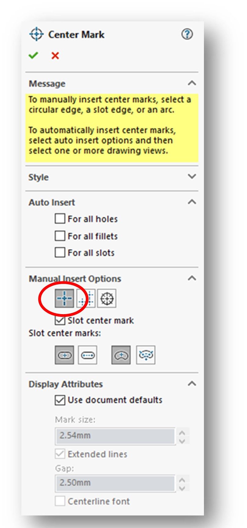
Note that in the Manual Insert Options roll-out, the Single Center Mark option is selected by default. You will be prompted to select a circular edge, a slot edge or an arc for the center mark insertion.
In lieu of manually inserting center marks, you can easily add center marks to multiple holes, fillets and slots in selected drawing views by selecting the respective checkboxes in the Auto Insert roll-out box of the Center Mark PropertyManager.
You can apply center marks to linear and/or circular patterns by selecting the Linear Center Mark or the Circle Center Mark options button in the Manual Insert Options roll-out. Ser the examples on Page 15-14.
Also note that you can select the way you want the center marks for your slots to appear. Do this by selecting one of the format options for slots located in the Slot center marks section of the Manual Insert Options roll-out. Read more about this at the bottom of Page 15-13.
ADDING CENTERLINES TO THE DRAWING VIEWS (page 15-15)
Don’t confuse centerlines with center marks! Centerlines are used to indicate symmetry, particularly on the orthographic views of cylindrical parts.
To add a centerline, select the Centerline button from the Annotation CommandManager. The Centerline PropertyManager will be displayed (see figure below):
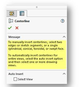
To manually insert a centerlines, you are prompted to select two edges or a single cylindrical face.
You can also automatically insert centerlines in a view by clicking the Select View checkbox located in the Auto Insert fly-out. Click on each view you want to automatically insert centerlines in.
Centerlines can be selected and deleted at any time after they are inserted.
Watch the video below to see how center marks and centerlines were added to an actual part drawing:
ADDING A HOLE CALL-OUT TO THE DRAWING VIEWS (page 15-16)
Hole callouts include one or more of the following attributes: hole diameter & depth, counterbore diameter & depth, countersink angle and depth, number of instances, thread geometry, fits, etc. There is specialized symbology which must be applied in accordance with the ANSI dimensioning standards.
The Hole Callout Tool can be used to simplify the generation of hole callouts for the holes you created at the Part level using the Simple Hole, Hole Wizard, Advanced Hole, or Extruded Cut tool.
To do this, select the Hole Callout button from the Annotation CommandManager. Your cursor will be replaced by the hole callout cursor. Select a hole from the drawing view. A proposed hole callout with a leader will be attached to the cursor (see Figure 15-20 on Page 15-16 and below):
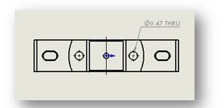
Pick a location on the drawing to place the callout by left-clicking your mouse. The Dimension PropertyManager will be displayed.
You can also create a hole callout for a slot feature.
ADDING COSMETIC THREADS TO THE DRAWING VIEWS (page 15-17)
Just read over. We don’t add cosmetic threads to drawings on this class.
ADDING THE MULTI-JOG LEADER TO THE DRAWING VIEWS (page 15-18)
Just read over. We don’t add the Multi-Jog Leader to drawings on this class.
ADDING THE DOWEL PIN SYMBOLS TO THE DRAWING VIEWS (page 15-18)
Just read over. We don’t add the dowel pin symbols to drawings on this class.
ALIGNING THE DIMENSION (page 15-19)
Often, we insert dimensions onto drawing views and they look like a “jumble” and may overlap. As you already know, the alignment of drawing dimensions are strictly controlled by ASME Y14.5 Dimensioning & Tolerancing. Solidworks has tools to help you get your dimensions properly aligned.
Follow the instructions given in this section to help align your dimensions.
To be honest, I just manually select and position my dimensions so that they comply with good dimensioning practices specified in ASME Y14.5 Dimensioning & Tolerancing. Go back and look over this specification if you need to refresh acceptable dimensioning practices.
EDITING DIMENSIONS (page 15-19)
You can edit annotations you added to a drawing view by selecting them or by double-clicking on them. As a result, their respective PropertyManagers or dialog boxes will be displayed allowing you to edit the parameters of the selected annotations.
You can also delete any annotation by selecting it and they clicking the DELETE key on your keyboard.
ADDING THE BILL OF MATERIALS (BOM) TO A DRAWING (page 15-20)
A bill of materials (BOM) is a listing of all the parts included in an assembly. Sometimes it is called a parts list. BOM is often pronounced “bomb”. Information such as part name, number of instances in the assembly, description, part number, and more can also be contained in the BOM. BOMs are only inserted in assembly drawings.
The BOM you place in an assembly drawing is parametric – meaning that when you add or delete a part from your assembly, those changes will be reflected in the BOM. Also, Solidworks pulls in (links to) the part name you give to your part models when you save them. In industry, we typically assign an actual part number to each part. For us, we just go with whatever we name them to keep things simple. So, you should be saving your part files that will go into assemblies using all capital letters.
As with dimensions and assembly numbers, BOMs are annotations. We build and insert BOMs by first selecting the Tables command found on the Annotation CommandManager. Then select the Bill of Materials option from the drop-down menu of options. This will open up the partial Bill of Materials PropertyManager which will prompt you to select a drawing view. Once you select a drawing view, the full Bill of Materials PropertyManager will open up (see Figures 15-26 & 15-27, Page 15-21). Accept the defaults by clicking the green checkmark at the top-left of the PropertyManager. The BOM will now be attached to your cursor. You may now select the location on the drawing where you wish to place the BOM. The individual cells, rows and columns in it can be easily edited and deleted as needed.
NOTE: Here at BC3 we almost always put the BOM in the lower right-hand corner of the drawing, just above the title block. The BOM has sort of “magnetic” property to it and it will “lock” into the lower right-hand corner when you get close to it.
We typically delete any blank columns in the BOM. For us, that is normally the DESCRIPTION column. To select or delete column: Right-click in the table and choose Select or Delete, then Column. Be care not to delete the entire BOM!
ADDING BALLOONS TO THE DRAWING VIEWS (page 15-23)
Well, we now have a drawing with an exploded isometric view in it and a BOM. We’re not done yet!
Assembly drawings typically include assembly numbers (“balloons”). In this section, we’ll learn how to insert assembly numbers (“balloons”) into our assembly drawing.
Assembly numbers identify each part inserted into an assembly. Note that these are not “part numbers”. Part numbers are assigned to a part by engineers or draftsmen when it is created and are unique to that part. Assembly numbers are automatically assigned to a part when it is inserted into the assembly. So, while a part only has one part number, it can have a different assembly number in each assembly it is used in – depending on the order in which the parts were added to the assembly.
Assembly numbers are created using the Balloon Tool located on the Annotation CommandManager. The Balloon PropertyManager will be displayed (see Figures 15-29 and 15-30 on Page 15-25). Also, your cursor will be replaced by the balloon cursor. Left-click on each part in the assembly and then left-click where you wish to place the balloon. You can reposition the balloons after you get all of them inserted. When you have all the balloons inserted, accept the defaults by clicking the green checkmark at the top-left of the PropertyManager.
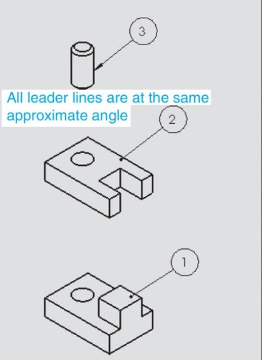
You can now go back and relocate any of the balloons by left-clicking on them and moving them. The leader remains attached to the part. You will see yellow alignment guides when you have a balloon selected that you can use to help align your balloons vertically.
NOTE: Try your best to make the angle of every leader line the same. This makes the drawing look more professional. Also, line up the balloons vertically (see figure below):
ADDING BALLOONS USING THE AUTOBALLOON TOOL (page 15-24)
We don’t use it in this class.
CREATING MAGNETIC LINES (page 15-26)
We don’t use it in this class.
ADDING NEW SHEETS TO THE DRAWING DOCUMENT (page 15-27)
Just read over. We don’t add sheets to our drawing documents in this class, but it is quite common in industry.
EDITING THE SHEET FORMAT (page 15-28)
Sheets need to be edited – particularly the Title Block information, including Drawn By, Scale, title, date, and more.
To edit a sheet, you need to activate it by selecting it in the FeatureManager Design Tree and choosing the Edit Sheet Format option from the short-cut menu. Note that the textbook says to choose the Activate option – this option does not display.
NOTE: Once your sheet is in edit mode, your drawing views will not be displayed. Do not be concerned – they have not been deleted! All you can edit at this point is the sheet, so the views are hidden.
You can edit any text in the title block by double-clicking on the text you wish to edit. Once you do that, the Notes PropertyManager will be displayed, the text will be highlighted and the Formatting toolbar will be displayed (see figure below):
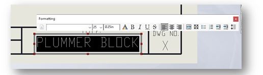
Click on the text once again and editing will be enabled. Note that your zoom tools work while in the edit mode. Once you have the text edited, click on the green checkmark in the top-left corner of the Notes PropertyManager to accept it.
Continue this process until all the title block information has been updated. You now close the sheet and end editing by clicking on it again in the FeatureManager Design Tree and choosing the Edit Sheet option. Your drawing views should now be restored.
CREATING USER-DEFINED SHEET FORMATS (page 15-28)
Most companies have their own pre-made drawing sheets/borders, similar to our BC3 sheets used in this class. Don’t spend any time on this section.
CONGRATULATIONS! YOU ARE DONE WITH CHAPTER 15!
