13 Assembly Modeling – II
CHAPTER 13 ASSEMBLY MODELING – II
This chapter builds on the material we covered in Chapter 12 on the Assembly mode of Solidworks.
There are a lot of topics in this chapter, but we will focus our attention on the following important concepts only:
- Edit assembly mates
- Using visibility options
- Checking interferences
- Creating an exploded state (view) of an assembly
This is not to say that there are not useful tools and techniques in the other sections of this chapter. We just do not have enough time in a single semester to cover everything. You are free to look everything over and use any tools that you find helpful.
Watch the video below in which various tools used in assemblies are demonstrated in an assembly called the Plummer Block. This video goes over some points about assemblies such as needing to keep bolts and nuts from rotating after assembly, how to change the color and/or transparency of parts in an assembly. Note that at 11:47 in the video I go over exploding the assembly and how to create a three-view orthographic assembly drawing directly from the assembly. These aspects of assemblies are covered in Chapters 13 and 14, respectively, and are only included in this video as a reference at this time.
:
EDIT ASSEMBLY MATES (page 13-13)
While doing your assembly modeling, you may have a need to edit one or more assembly mates that you have already placed into your assembly. The edits that you can do include: modifying the type of mate applied, the angle or offset values, changing the component the mate is applied to, and more.
To edit mates, expand the Mates node located on the FeatureManager Design Tree. This is where all the mates in your assembly are located. Next, elect the mate you wish to edit. A pop-up toolbar will be displayed. Choose the Edit Feature option from the toolbar. This will activate the appropriate Mate PropertyManager with the Mates option pre-chosen. (See figure below and Figure 13-20, Page 13-13).
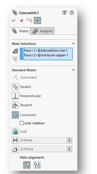
Editing an existing mate is similar to how you originally created it. Select the aspect of the mate you wish to edit from the Mate PropertyManager and proceed with the edit.
Watch the following YouTube video covering how to identify the mates in your assembly and how to edit them:
SIMPLIFYING ASSEMBLIES USING THE VISIBILITY OPTIONS (page 13-27).
Sometimes while creating your assembly model, it becomes advantageous to change the visibility of some of the components. This involves either making a component transparent (clear) or completely hiding a component. You can also suppress (and unsuppress) a component, but we don’t use that capability very often in this class.
HIDING COMPONENTS (page 13-27)
In order to hide a component in an assembly, select the component by clicking on it in the drawing area or by selecting it from the FeatureManager Design Tree. NOTE: If you hold down the CTRL key you can select multiple components to hide in a single step. Then choose the Hide Components option from the pop-up toolbar.
When you hide a component, the display of the component will be turned off in the assembly. Its icon in the FeatureManager Design Tree will be made transparent as well. Hiding a component does NOT delete it from the assembly! Its still there, you just can’t see it in the assembly.
So, what if you want to unhide a component? You can do that by selecting the icon in the FeatureManager Design Tree for the hidden component. Then choose Show Components from the pop-up toolbar.
Watch the following YouTube video illustrating how to hide and show components in an assembly:
CHANGING THE TRANSPARENCY CONDITIONS (page 13-28)
Sometimes you don’t want to fully hide a component, but you’d like to make it transparent (clear). This is often done in assemblies that have components enclosed in an enclosure to permit us to see what’s going on inside.
Watch the following YouTube video illustrating how to change the transparency of components in an assembly. We often you this to make mating easier or to allow visibility into an assembly.
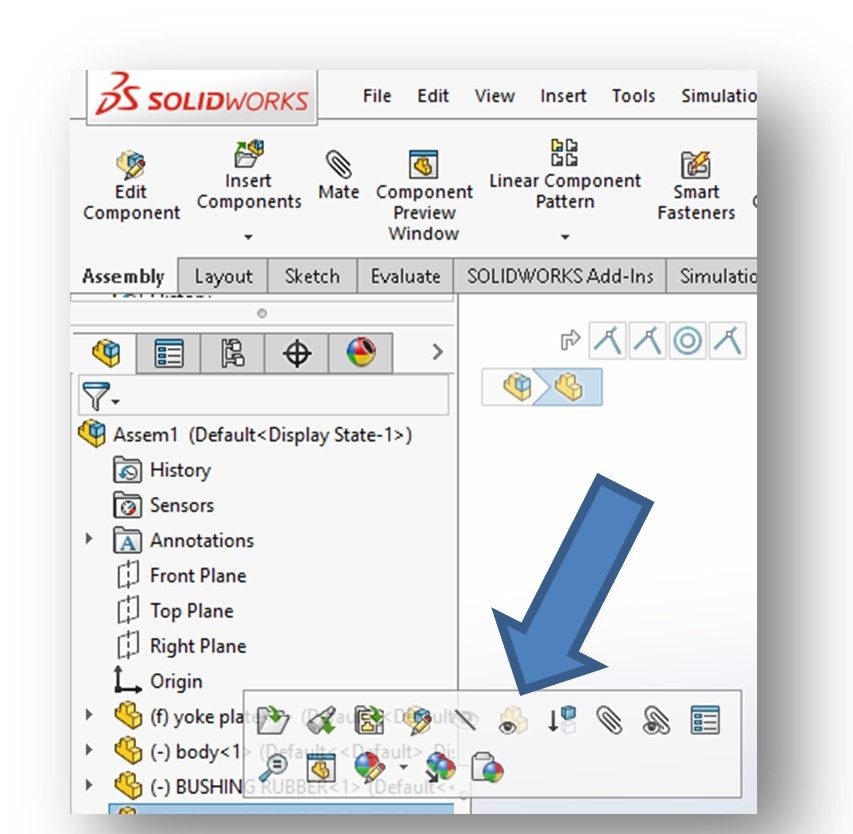
To change its transparency, select the component by clicking on it in the drawing area or by selecting it from the FeatureManager Design Tree. Then choose the Change Transparency option from the pop-up toolbar (see figures below).
NOTE: If you have previously applied a color to the component you are making transparent, the component will still be displayed with a tinge of the selected color. This can be a cool effect.
CHANGING THE DISPLAY STATES (page 13-28)
In the assembly environment, it is possible to display different components in different display states. This would allow you to create different states of the same assembly in which the color and/or transparency of the various components differ. This can also be used to create an exploded view of an assembly.
Watch the following YouTube video describing how to set up different display states for your assembly. The presenter uses a lawnmower to show how you can “paint” each part in your assembly a different color and then save that “picture” as a discrete display state. An assembly can have multiple display states.
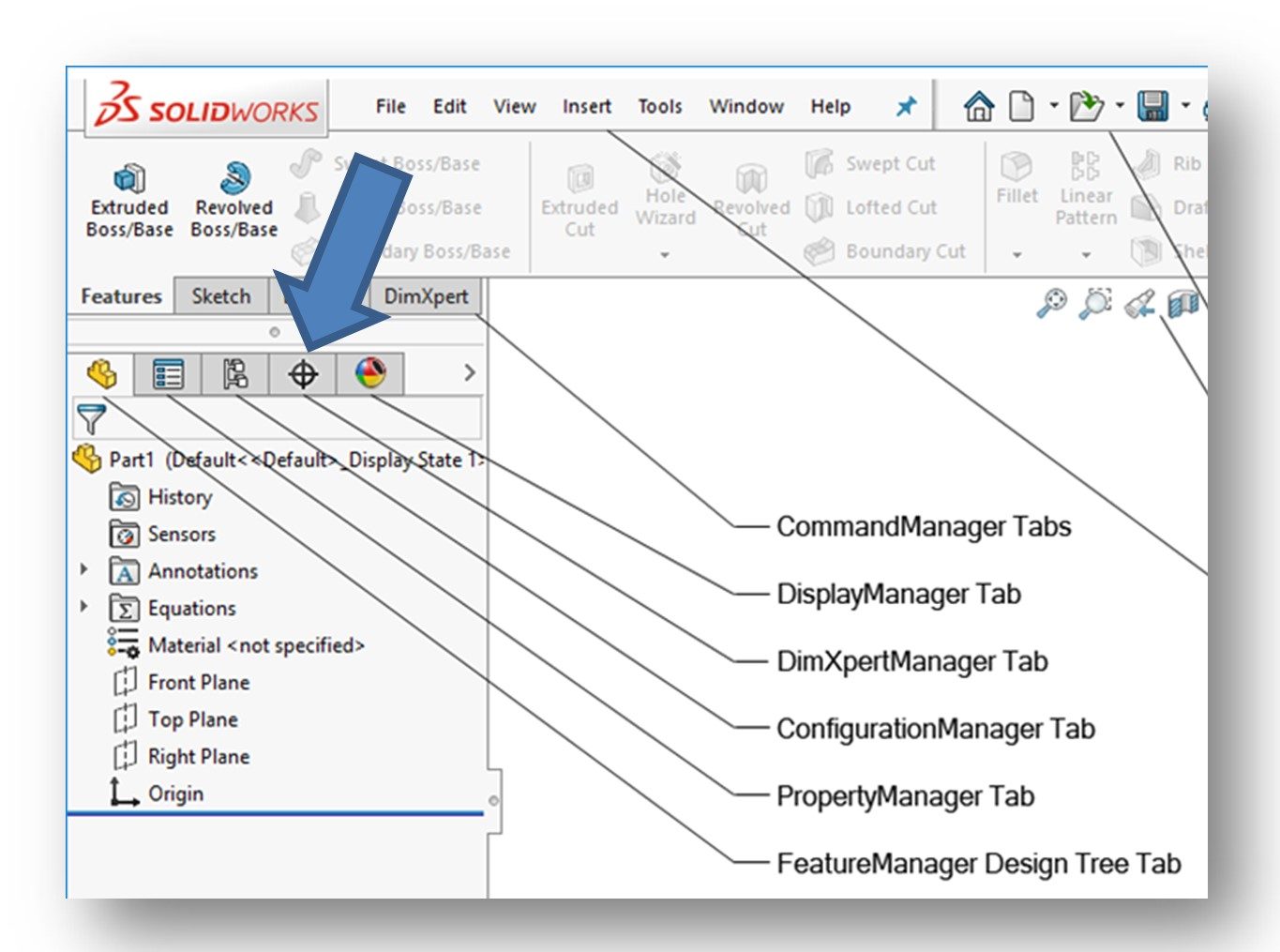
To create different state, invoke the ConfigurationManager located above the FeatureManager Design Tree (see figure below).
In the Display States section at the bottom of the Configurations PropertyManager box (see figure below), left-click on the default display state to select it.
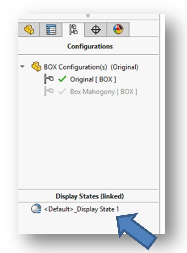
Then right-click to display a short-cut menu. Choose the Add Display State option. This will create a new display state. The display states are numbered progressively as you add them. States can be renamed by selecting Properties from the pop-up menu. You can also delete unwanted display states by selecting the state and selecting Delete Display State from the short-cut menu.
Once you have a new display state added, invoke the FeatureManager Design Tree and change the display state(s) of the component(s). Invoke the ConfigurationManager again and double-click on the inactive state to see the changes you made.
NOTE: These display states are basically different configurations of the same assembly and they exist side-by-side with each other. Changing one display state does not change any of the other display states. You can only view one display state at a time. You select which display state you wish to see or use to create a drawing from (we’ll cover assembly drawings in a later chapter) by using the ConfigurationManager.
ADDING COLOR TO COMPONENTS (not in textbook)
Sometimes we want to add color to one or more of the components in an assembly. We could go back to the individual part models and color the part, but normally we do this at the assembly level. This will not add color at the part level.
Adding color to a component is not covered in the textbook. To color a part, we change its appearance. Start out by selecting the part you wish to color by left-clicking on the part in the FeatureManager Design Tree. A pop-up menu will become visible (see figure below):
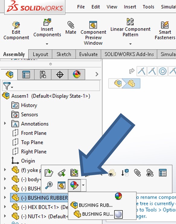
Select the Appearances option (the “basketball”) from the menu. Another small pop-up menu will be displayed that gives you the option to color the part at the assembly level or back at the part model level. Click on the assembly icon.
The Color PropertyManager will be shown (see figure below):
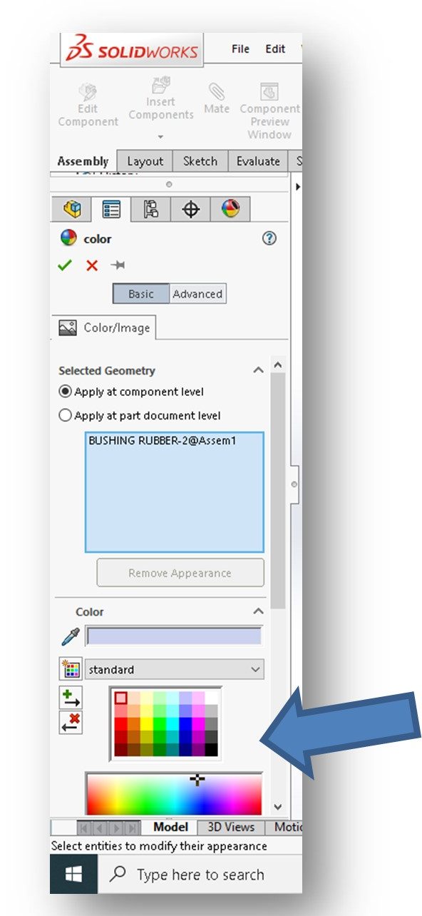
Click to select the color you wish to add from one of the color palettes near the bottom of the PropertyManager. The top palette contains 40 pre-set colors – I typically select one of those. The bottom palette contains an almost infinite number of colors from which you can select. When a color is selected, the part in your assembly will be updated to depict that color. If you like what you see, click the green checkmark at the top of the PropertyManager to accept the color.
Part colors can be deleted or modified at any time using this same routine.
CHECKING INTERFERENCES IN AN ASSEMBLY (page 13-28)
When you assemble parts in the physical world, no two parts can occupy the same space. That should make sense. But Solidworks will let you assemble parts together even if they interfere with each other! Luckily, the software provides a tool that allows you to easily check for interferences.
I typically don’t make students run interference checks, but it would be a best practice to do so. Look over this section and I recommend you try it on one of your assignments – just to see how it works. Its pretty easy to do. I will not ask you to do this on a test.
CREATING EXPLODED STATE OF AN ASSEMBLY (page 13-34)
Up to this point, we’ve been just creating assemblies. Now, what do we do with them?
Watch the YouTube video titled “Solidworks Quick Tip – Working with Exploded Views in Assemblies”:
Typically, we create exploded assembly views and place them in drawings for use on the shop floor to aid in assembly. I’m sure all of us have put together furniture from IKEA (with that annoying little Allen wrench!!). The product engineers at IKEA are experts at using exploded view drawings to help us all build stuff at home without a single word of instruction!
Below is fun example – can you spot the problems with this assembly and its parts????

Of course, other product manufacturers do the same thing. On the shop floor we often provide exploded view drawings to help assemblers build the product quickly, easily and correctly. Exploded views are also used in technical/repair manuals, installation manuals, and other technical documentation.
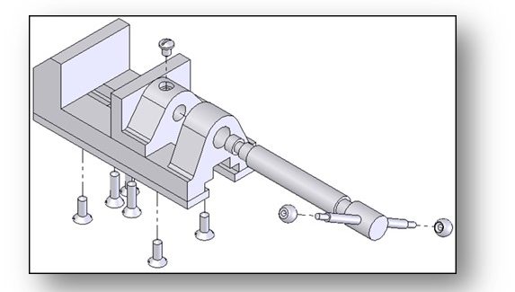
So, what is an “exploded assembly state”? In this assembly state, the components that make up the assembly are pulled apart (“exploded”) such that it is easier to see how they go together. See example below:
Back in the “old days” before modeling programs like Solidworks were available, companies employed specialists called Technical Illustrators to manually draw these exploded views. This was very labor intensive and were difficult to modify should changes to the design be made. The EXPLODED VIEW tool in Solidworks make the creation of exploded assemblies a snap! Lets see how we do it…..
The Explode PropertyManager is used to created exploded assembly states in Solidworks. To invoke it, select the Exploded View command icon from the Assembly CommandManager (see figure below).
The Explode PropertyManager will be displayed (see figure below and Figure 13-52, Page 13-34):
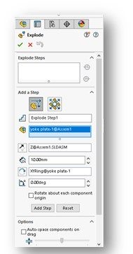
There are two explode routines – (1) Regular step (translate and rotate) and (2) Radial step. The Regular step routine is selected by default. That’s good because we exclusively use the Regular step explode routine in this class. Tutorial 1 (page 13-39) illustrates how to do a Radial step explosion.
REGULAR STEP (TRANSLATE AND ROTATE) (page 13-34)
In this explosion routine, parts are exploded away from each other in a straight line. The parts can also be rotated during the explosion as well.
An assembly is exploded in steps. The movement of each component constitutes a step. In theory, you should only have as many explosion steps as there are components in your assembly. One of the big mistakes new users make is creating numerous superfluous steps by going back to their previous explosion steps in an attempt to touch them up. Steps can be edited once they are created and you need to follow the appropriate editing steps. More on that later.
NOTE: Before starting an explosion, think through how you want to position each part. There’s typically a logical “first part” to explode. The base part of your assembly typically is not moved during an explosion.
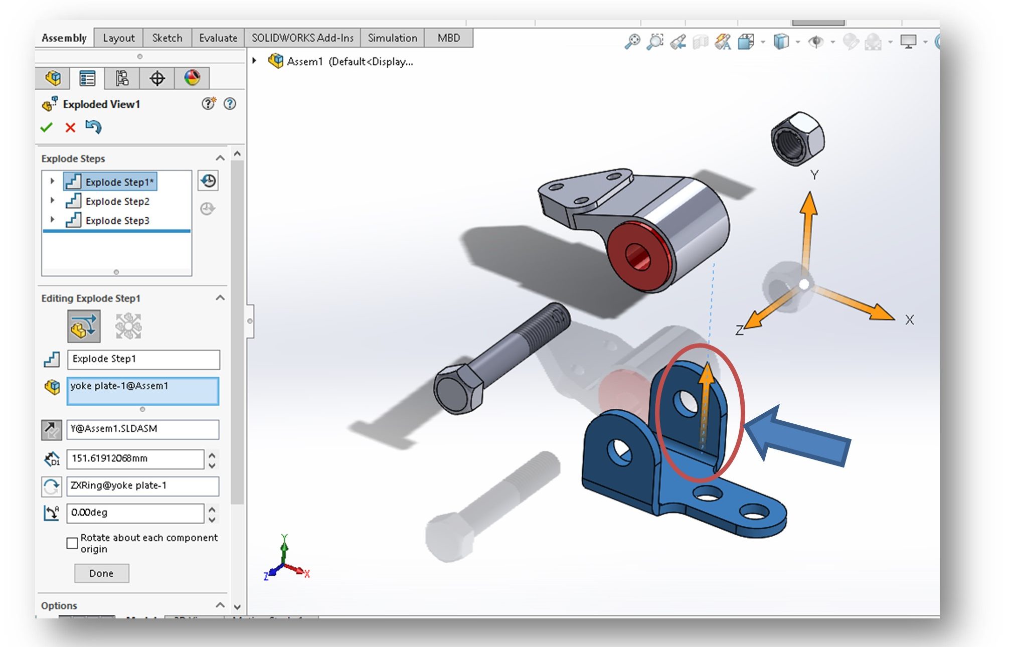
First, select the component in the assembly you wish to explode. This can be done by clicking on the part in the assembly itself. You can also click on the part in the Design Tree. Once selected, an orange-colored triad will be displayed on the part – this is called the “Manipulator”. (see figure below). The name of the selected part will also be shown in the Explode Step Components selection box of the Add Step rollout.
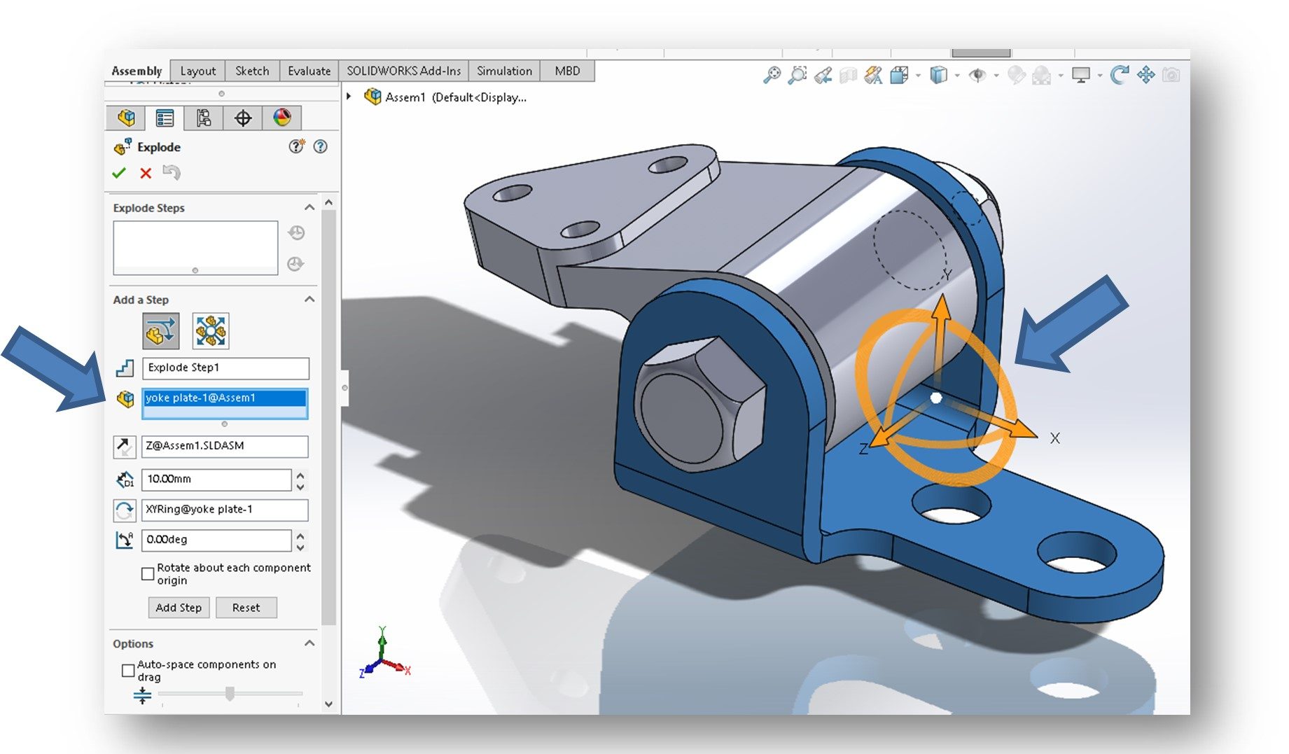
The Manipulator triad is used to “translate” the part – or move it in a linear direction. To explode the selected part along any of the three axes of the triad, simply move the cursor over the arrowhead of that axis. The selected axis arrow will turn blue, indicating that it is now a “move” axis. Click and hold down the left mouse button to grab the arrowhead. Now drag the cursor to explode the component.
NOTE: Be sure to keep the left mouse button down until you have moved the part to the desired exploded position. New users get in trouble when they release the button too early and fail to reach the desired exploded position.
When the part is in the desired exploded position, release the mouse button. You have now added a step. Steps are progressively numbered. The first move you make is Step 1, the next is Step 2, and so on. If your part is not quite in the desired position, you can adjust the position, but only along the axes you originally selected. Once you are happy with the move, click the DONE button.
NOTE: DO NOT CLICK THE GREEN CHECKMARK if you have more parts to explode!!
Once the DONE button is clicked, Step 1 is created and Step 2 is teed up for creation. Follow the same routine as we did for the first step. Keep creating explosion steps until all parts are in the positions you desire.
NOTE: We typically explode an assembly such that parts do not overlap each other after the explosion is complete. Sometimes this just isn’t possible, but it is the goal of a good explosion.
When all parts have been exploded to their desired positions, click the green checkmark at the top of the PropertyManager to accept the move. If you don’t like the explosion at all, click the red “X” to start completely over. Keep in mind that we can go back and edit individual steps once the explosion is created (see below).
Once you click the green checkmark, an exploded display state (configuration) is created. You can create multiple explosion configurations, but we limit ourselves to a single one in this class to keep it simple.
EDITING EXPLOSION STEPS (not in text)
So, what if you want to go back and edit one or more of the explosion steps you created? How do we do this? The textbook doesn’t really cover this so I will attempt to explain it here.
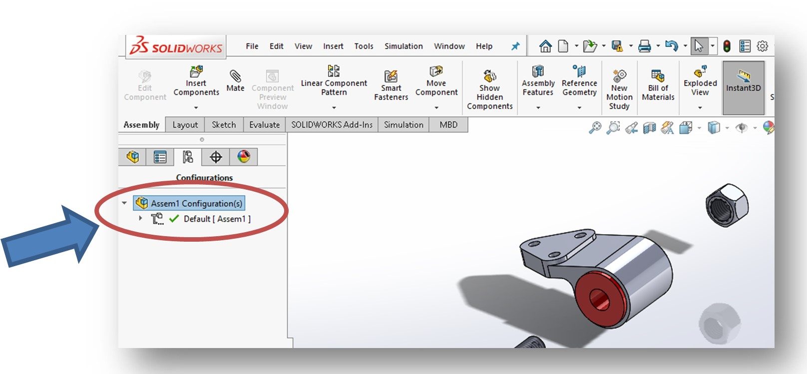
As I said, once you click the green checkmark, a new configuration of the assembly is created. You can access this configuration by invoking the Configuration Manager located above the FeatureManager Design Tree (see figure below):
This will display the Configurations PropertyManager (see figure below). At the top of the box is the Assembly Configurations. Note that a default configuration is displayed – this is the collapsed state of the assembly.
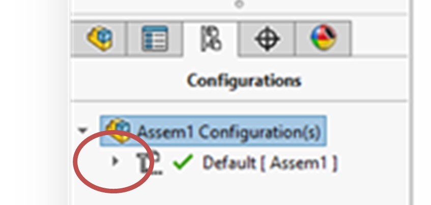
The exploded configuration(s) can be displayed by clicking the down arrow in front of the default configuration (see figure below):
Once the down arrow is clicked, all of the exploded views you have created will be displayed. In reality, there should only be one.
The steps in the exploded view can be displayed by clicking the down arrow in front of the Exploded View (see below):
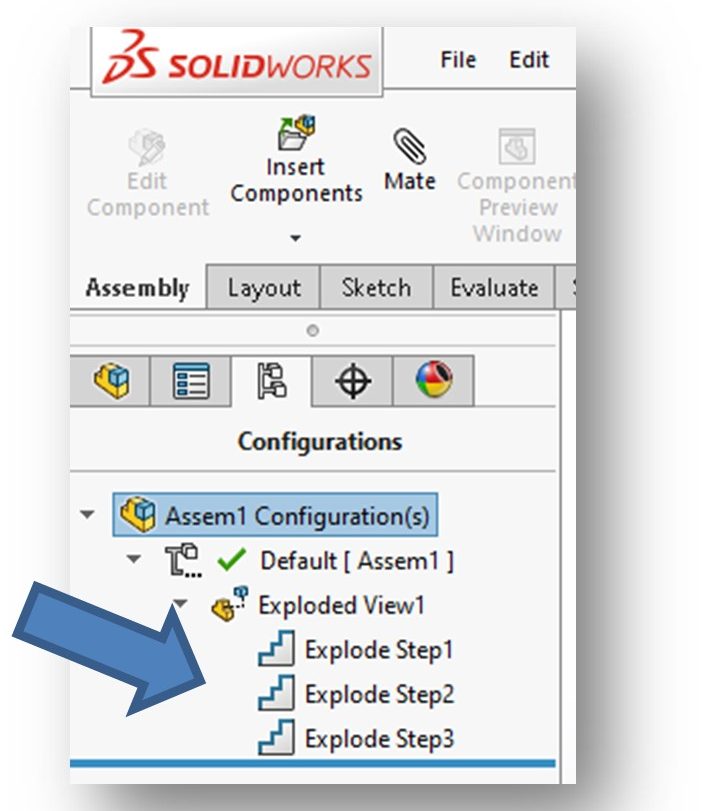
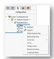
These steps can be selected and edited. To do so, right-click on the step you wish to edit. From the pop-up menu that displays, select the Edit Explode Step option (see below):
This will display a PropertyManager for the specific step you have selected for editing (see figure below). It operates identically to the general Explode PropertyManager used to originally create the step. The direction arrow for the axis originally used to create the step will appear on the part in orange. You can only edit the position along this axis.
When you are done editing the step, click the DONE button and then the green checkmark. To edit additional steps, repeat the previous steps.
NOTE: If you have multiple exploded views when you open the Configuration, you need to look at each and delete those that are superfluous.
CONGRATULATIONS! YOU ARE DONE WITH CHAPTER 13!
