7 Advanced Modeling Tools – I
CHAPTER 7 ADVANCED MODELING TOOLS I
This chapter builds on what we learned in Chapters 5 and 6. It provides a method for creating additional specialized features, including:
- “simple holes” (using the Simple Hole tool),
- “standard holes” (using the Hole Wizard),
- threads,
- fillets,
- chamfers,
- and shells
CREATING SIMPLE HOLES (page 7-2)
In Chapter 6, we learned to create simple holes (no threads, counterbores, countersinks, etc.) by extrude-cutting a circle into a part. In this method, the circle had to be sketched before doing the Extruded Cut operation. In this section the Simple Hole tool is introduced which does not require that the circle be sketched first, thus saving you a step in the process. Holes produced with this new process are features. I rarely use this method, but you can use it if you wish.
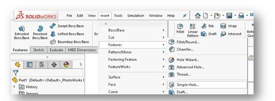
To start out, you must first select the planar surface you wish to place the hole feature on. This is no different than what we did in Chapter 6. Then go the Solidworks menus at the top of the screen and click on the Insert tab. From the drop-down menu, click on the Features option. Then select the Simple Hole…. tool. See below:
NOTE: If you did not pre-select a plane on which to place the hole, you will be prompted to select a placement plane. So, select a plane to place the hole feature on. This can be any planar surface on the model or a default plane.
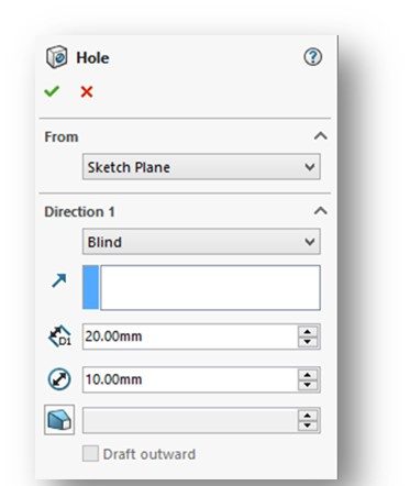
The Hole PropertyManager should now be displayed (Figure 7-1, Page 7-2 and below). Note that the options are very similar to what we saw in the Extruded-Cut tool back in Chapter 6.
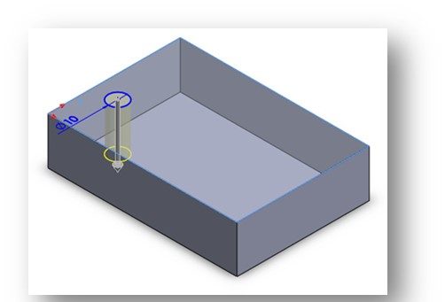
You should see a preview of the hole feature on your model with temporary graphics. It will reflect the default values and options in the Hole PropertyManager (See Figure 7-2, Page 7-2 and below).
Just like we did in Chapter 6, you need to specify the parameters for the hole that meet the design intent. This would include the Hole Diameter, End Condition, Depth (if needed), Draft (if needed), etc. Click the green checkmark to create the hole feature. A Hole feature should now show up in the Design Tree. (If you use the extruded-cut method from Chapter 6, the feature added is just a generic Cut Extrude feature). Note that there will be a sketch associated with this Hole feature, even though you technically did not create one. This sketch must be defined.
NOTE: You need to left click on the sketch and select the Edit Sketch option from the pop-up toolbar and apply relations and/or Smart Dimensions to define the location of the hole feature on the previously selected surface. If properly located, the circle on the face should turn black (fully defined).
Is this really easier than just using the Extruded-Cut method we discussed in Chapter 6? You decide for yourself and use what method works for you. One is not any better than the other.
CREATING STANDARD HOLES USING THE HOLE WIZARD (page 7-3)
Okay, so we’ve established a couple of different ways to construct “simple holes”. And, simple holes are the MOST common features in mechanical parts. Make sure you can expertly create them.
But, what if we need a more sophisticated hole? Like one with threads? Or has a counterbored or countersunk inlet? We certainly do not want to try and model all that additional complexity ourselves – that would be way too labor intensive. So, to loosely take-off on something Elizabeth Warren said during the 2020 Presidential campaign – “we have a tool for that” – the Hole Wizard. It even does simple holes!
The Hole Wizard is a very powerful tool. With it, you can control all the parameters of the hole. There’s even an Advanced Hole option that allows you to do even more. Its covered starting on Page 7-9 but we don’t use that functionality this semester.
Watch the following YouTube video covering the Hole Wizard tool in Solidworks:
To get started, you must first select the planar surface you wish to place the hole feature on, just like we did using the Hole tool earlier in this chapter. Then chose the Hole Wizard button from the Hole Wizard flyout on the Features CommandManager (see below):
The Hole Specification PropertyManager will be displayed (Figure 7-3, Page 7-4 and below). Note that there are two tabs – Type and Position. I typically do Type first.
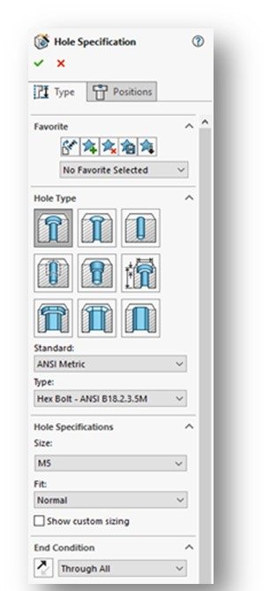
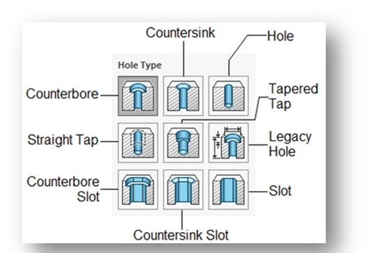
Under the Type tab, we define the type of standard hole we want to create. There are 9 “standard” hole types available. They are pictorial depicted in the Hole Type rollout. (See Figure 7-4, Page 7-4 and below). Note that Counterbore is preselected as the default hole type – its one of the most common hole types. Countersink is the other.
The next rollout is termed Standard. This is where we select the industrial dimensioning standard for our holes. By default, the ANSI Metric standard is selected. This standard has all the metric (“M”) size fasteners. Others available in the drop-down list include: ANSI Inch, AS, BSI, DIN, GB, IS, ISO, JIS, and more. For our familiar “inch” based fasteners, we use the ANSI Inch standard.
Next on the list is the Type rollout. This drop-down list is used to define the type of fastener that will ultimately be put into the hole we are creating. It is noted here that the hole is created based on the fastener it will be receiving. This should make sense as the hole and the fastener must match! The types of screws and bolts available in the drop-down list depends upon which standard you select in the previous Standard rollout. Plus, only those fasteners that match the hole type selected in the Hole Type rollout will be displayed in the drop-down list.
The next section is the Hole Specification rollout. It is where we define the size and fit of the standard hole to be created. Size is pretty self-explanatory – for example, we’re using a ¼-20 bolt so we select the “1/4” size option. Fit is used to define how the fastener interface with the hole. It is a measure of tightness or looseness between them. Solidworks only gives us three generic options: Close, Normal or Loose. Most of the time we select the “Normal” option.
End Condition is the next rollout. This is similar to the termination selections in the Extruded-Cut and Extrude Boss/Base commands from previous chapters. Select it carefully in order to capture the design intent!
We don’t use the next 2 rollouts: Options (if presented) and Tolerance/Precision.
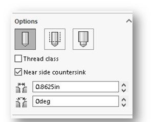
If you selected a Straight Tap hole in the Hole Type rollout, you will also be presented with options for specifying how the internal threads of the hole will be presented on any drawings we create from the part model at a future time (see below). These will show up in the Options rollout (see right). The Cosmetic Thread option is typically selected.
If you click the Thread Class checkbox, the thread fit (“fit”) of the threads can be specified. Fit is used to define how the threads on the fastener interface with the threads in the hole. It is a combination of allowances and tolerances and a measure of tightness or looseness between them. For Unified inch (UNC and UNF) screw threads – typically used in the USA – there are six standard classes of fit: 1B, 2B, and 3B for internal threads; and 1A, 2A, and 3A for external threads. All are considered clearance fits. That is, they assemble without interference. The higher the class number, the tighter the fit. 1B is considered “very loose”, 2B is “normal”, and 3B is “tight”. Solidworks Most of the time we select the “2B” option. Note that Metric fasteners have a similar fit routine as well – called tolerance classes – but Solidworks doesn’t provide a method for specifying it.
DEFINING THE POSITION FOR PLACING A HOLE (page 7-7)
Now that we’ve got the hole defined, its time to specify the location of the hole(s). To do so, choose the Positions tab from the top of the Hole Specification PropertyManager.
The Hole Position PropertyManager will be presented. It will direct you to use dimensions and/or sketch tools to specify the position of the hole(s).
You can read all the stuff in the text, but I simply use Smart Dimenstions to specify the center position of each hole (vertical and horizontal). Remember that these holes are features, thus they will not define out like a hole does in a sketch.
Watch the following YouTube video discussing how to precisely place holes on a surface when using the Hole Wizard functionality in Solidworks:
CREATING ADVANCED HOLES (page 7-9)
It is unlikely we will use this functionality this semester. Just read it over.
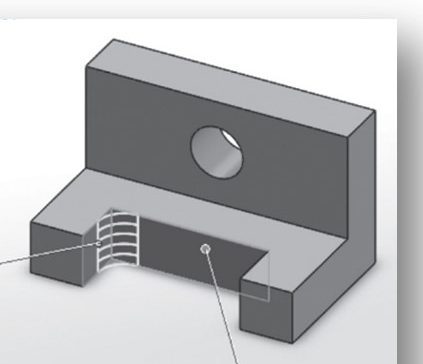
CREATING THREADS (page 7-12)
This section discusses how to create external threads on cylindrical surfaces. It is unlikely we will use this functionality this semester. Just read it over.
CREATING FILLETS (page 7-16)
Way back in Chapter 3 (see Page 3-8) we learned how to create fillets in a sketch. The reality is that we seldom do that. We normally add fillets as features in the 3D model. This is much easier to do and also much easier to modify later (its easier to modify a feature in a model than to go back and edit a sketch!). This supports the old 3D modeling adage: “Whenever possible, create Features rather than Sketch Entities”.
Watch the following YouTube video on creating fillets (as features, not in the sketch) in Solidworks:
There are two ways to create fillet features in a model – manual method and the FilleteXpert. I only use the manual method. Using the FilleteXpert is covered starting on Page 7-35 if you are interested. I’m not going to cover it in this guide.
To create a fillet feature using the manual method, first select the Fillet tool from the Features CommandManager. Then select the Fillet option from the drop-down menu. Note that the Fillet and Chamfer tools share the Fillet command icon.
The Fillet PropertyManager will be displayed (Figure 7-27, Page 7-17 and below). Make sure the Full Preview radio button in the center of the manager is selected – believe me, you’ll want to see a real-time preview of your fillets as you create them on your model.
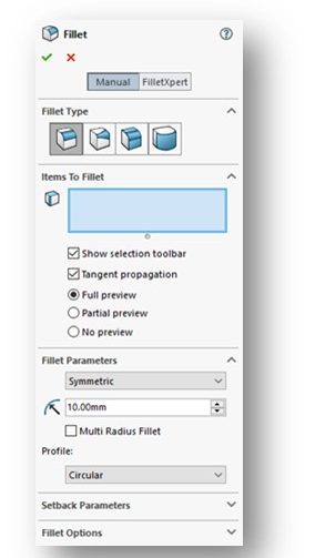
Figure 7-27 Fillet PropertyManager
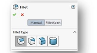
Click the Manual button at the top of the manager to enter the manual creation mode.
The first rollout is Fillet Type. This rollout pictorially depicts the 4 different types of fillets that can be added to your model (see right). These are: Constant Size, Variable Size, Face, and Full Round (see below):
CREATING CONSTANT SIZE FILLET (page 7-17)
Most of the fillets we create are of the Constant Radius type. This type of fillet is created by using the edge line where two faces (surfaces) meet (see below):
To create, we select the edge line where the two surfaces meet. You specify the radius of the fillet in the Fillet Parameters rollout. If your preview looks okay, accept all other defaults and click the green arrow to create the fillet.
There’s lots of other options on Pages 7-18 through 7-26. I don’t use them very often, so just read them over. It is unlikely you’ll need them in this class this semester.
CREATING VARIABLE SIZE FILLET (page 7-27)
We hardly ever use the Variable Radius type. Just read over.
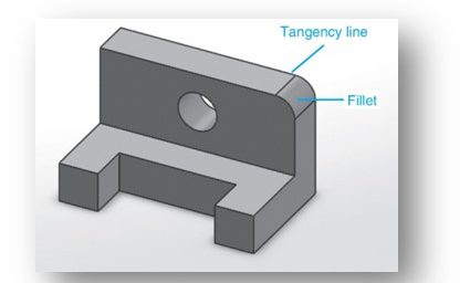
CREATING FACE FILLET (page 7-29)
Face Fillets are similar to Constant Radius type fillets in that they too are used to create fillets between faces (surfaces) of a part.
With this type, we select the two faces we want to use. You specify the radius of the fillet in the Fillet Parameters rollout. If your preview looks okay, accept all other defaults and click the green arrow to create the fillet.
There’s lots of other options on Pages 7-29 through 7-31. I don’t use them very often, so just read them over. It is unlikely you’ll need them in this class this semester.
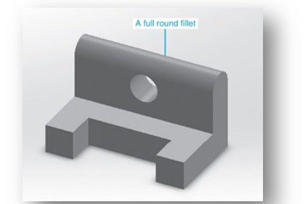
CREATING THE FULL ROUND FILLET (page 7-32)
The Full Round Fillet type can be used to round-over a surface. We don’t use this type very often, but it can come in handy.
CREATING FILLETS USING THE FILLETEXPERT (page 7-35)
As mentioned earlier, I don’t use the FilleteXpert to create fillets. I do them using the manual method. You can read this over and use it if you wish.
A NOTE ABOUT EDITING FILLETS:
Fillets produced as features can be easily edited. To edit, right-click on the fillet in the Feature Manager Design Tree and select the Edit Feature command icon in the top left-hand corner. This will open up the Fillet PropertyManager where you can edit all the fillet properties.
CREATING CHAMFERS (page 7-36)
We talked about chamfers back in Chapter 3 (see Page 3-9) when we introduced the Chamfer sketching tool as a mthod of creating chamfers in our sketches. The reality is that we seldom do that. We normally add chamfers as features in the 3D model. This is much easier to do and also much easier to modify later (its easier to modify a feature in a model than to go back and edit a sketch!). This supports the old 3D modeling adage: “Whenever possible, create Features rather than Sketch Entities”.
As a review, chamfers are angled surfaces added to a corner of an object. Most chamfers are at a 45o angle (sides are equal), but there are other configurations. They are defined by either (1) an angle and a distance (ie., 5 x 45o) or (2) two distances (ie., 5 x 5). When using two distances, they can be equal or different.
This section covers the basic methods of creating 3 different types of chamfers.
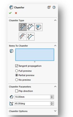
To create a chamfer feature using the manual method, first select the Fillet tool from the Features CommandManager. Then select the Chamfer option from the drop-down menu. Note that the Fillet and Chamfer tools share the FIllet command icon.
The Chamfer PropertyManager will be displayed (Figure 7-88, Page 7-37 and below). Make sure the Full Preview radio button in the center of the manager is selected – believe me, you’ll want to see a real-time preview of your fillets as you create them on your model.
I’ll let you read over the information on Pages 7-37 through 7-42. Pay particular attention to how an Edge Chamfer is constructed using an angle and a distance (top of Page 7-37). This is the most common chamfer we create.
Look over how to create a chamfer using two distances (bottom of Page 7-37). We see these occasionally.
Don’t spend any time on creating a Vertex Chamfer (Page 7-38) or how to create a Face Chamfer (page 7-39).
A NOTE ABOUT EDITING CHAMFERS:
Like fillets, chamfers produced as features can be easily edited. To edit, right-click on the chamfer in the Feature Manager Design Tree and select the Edit Feature command icon in the top left-hand corner. This will open up the Chamfer PropertyManager where you can edit all the chamfer properties.
CREATING SHELL FEATURES (page 7-42)
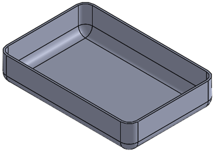
Shelling is a process in which material is “scooped” out of a model. The result is a hollow model with walls of a specified thickness and an internal cavity (see below). Many enclosures and cases are “shells”. We don’t use this capability very often in this class, but its worth looking at.
Watch the following YouTube video on using the Shell Tool in Solidworks:
Shells are features. To create a shell, invoke the Shell tool from the Features CommandManger. The Shell PropertyManager will be displayed (Figure 7-107, Page 7-42 and below):
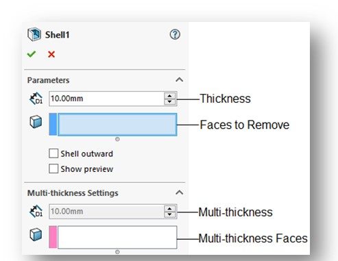
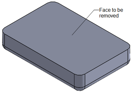
You will need to select the face(s) you wish to remove as a result of the shell operation. This is done in the Parameters rollout. If no faces are selected, you will get a closed, hollow model.
You set the wall thickness in the Parameters rollout. We typically only use a single wall thickness for the entire shell, but multiple wall thickness can be specified.
CREATING WRAP FEATURES (page 7-45)
It is unlikely we will use this functionality this semester. Just read it over.
CONGRATLUATIONS! You are done with Chapter 7!
