12 Assembly Modeling – I
CHAPTER 12 ASSEMBLY MODELING – I
This chapter introduces us to the second mode of Solidworks – “Assembly”. I think working with assemblies in Solidworks is where you can have the most fun.
In this chapter, we will learn how to:
- Create bottom-up assemblies
- Use “mates” to assemble parts together and properly constrain them
- Move and rotate individual components
ASSEMBLY MODELING (page 12-2)
An assembly consists of 2 or more components assembled together in the positions they occupy when the assembly is used by using parametric relations. In Solidworks, these relations are called “mates”.
Mates allow the user to constrain the degrees of freedom (DOF) of the components. For example, once assembled, a bolt should not be able to move in (or out of) its respective hole, so it must be constrained in the assembly such that it cannot move in this fashion. We’ll talk more about assembly mates starting on Page 12-9.
Watch the YouTube video below to get acquainted with creating assemblie sin Solidworks:
To start the Assembly mode, invoke the New Solidworks Document dialog box (see below and in Figure 12-1, Page 12-2) and selecting the Assembly button.
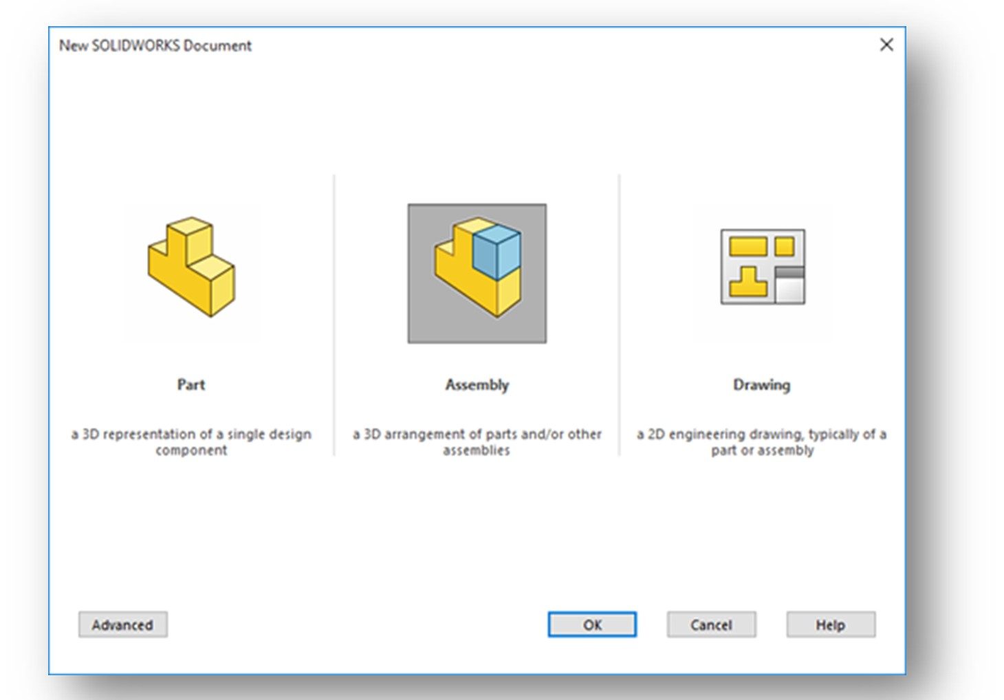
After clicking the OK button at the bottom of the dialog box, a new document will open in the Assembly mode.
The Begin Assembly PropertyManager and the Open dialog box will be invoked. (see below and Figure 12-2, Page 12-3). Note that the Assembly tab of the Command Manager will be selected.
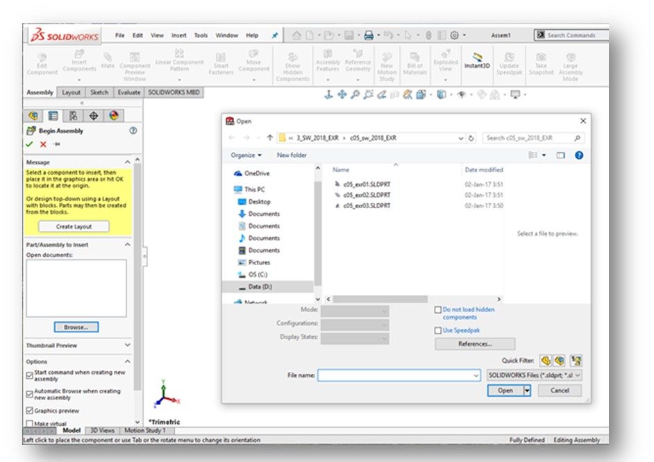
We’ll get into this dialog box a little later. It basically is asking you to select the first part to insert into your assembly – this is called the Base Part. Again, more later on this….
TYPES OF ASSEMBLY DESIGN APPROACH (page 12-2)
There are two different approaches to creating assemblies in Solidworks:
- Bottom-up, and
- Top-down
We’ll only talk about and use the bottom-up approach in this class. Keep on reading…..
BOTTOM-UP ASSEMBLY DESIGN APPROACH (page 12-2)
Bottom-up is the traditional and most commonly used of assembly design. So, that’s what we’re going to focus on in this course.
Bottom-up assemblies are created using existing Solidworks parts (.sldprt) which have already been modeled. It is possible to model parts and then create an assembly right from the part and/or create parts while in an assembly, but this is not how we are going to approach it.
Most assemblies we create in industry are bottom-up anyway. Often, multiple people create the parts that go into an assembly. Seldom does one person in industry model every single part that goes into an assembly. Also, we often incorporate model for parts we get from suppliers (or potential suppliers) such as fasteners and other standard hardware that we buy rather than make in-house.
CREATING BOTTOM-UP ASSEMBLIES (page 12-3)
When we use the bottom-up approach, we insert previously-created individual parts into the assembly. These parts are created in the Part mode. These parts are assembled together using Assembly Mates.
We start out a bottom-up assembly by placing the first (or Base) part into the assembly.
NOTE: I want to note here that the selection of the first part to insert into an assembly is pretty important. It serves as the “anchor” for the other parts. Typically, its pretty obvious which part should be inserted first. But sometimes you have to look over the parts you’re going to assemble and think about which one you’d start with if you actually had the parts in front of you to assembly together.
This base part is inserted such that the origin of the base part is aligned with the origin of the assembly. By doing this, the default planes of the part and the assembly are aligned. We talk about how to do this in the next section.
The base part is fixed in position when it is inserted. This fixes your entire assembly in the assembly workspace. We talk about how to do this in the next section. When you mate other parts to the base part, they are fixed in position by default without having to fix them. Parts that are not fixed are floating.
PLACING COMPONENTS IN THE ASSEMBLY DOCUMENT (page 12-4)
NOTE: Before starting your assembly, be sure that all the component parts you plan to insert are located in a single folder that you ultimately will save your assembly document into.
There are various methods for inserting parts into an assembly. We typically insert parts using the PropertyManager, so that’s the one we’ll focus on in this guide. The other methods are in the textbook.
PLACING COMPONENTS USING THE PROPERTYMANAGER (page 12-4)
As we showed previously, when you start a new Assembly in Solidworks, the Begin Assembly PropertyManager will be displayed (see below and Figure 12-3, Page 12-4).
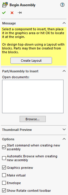
The Message rollout section gives you direction. In a nutshell, you activate the Part/Assembly to Insert rollout by clicking on the Browse button. This will display the Open dialog box in which you can browse your files for the first (base) part to be inserted into the assembly. Once you find the part you wish to insert, click the Open button. Note that if you have a part already open in Solidworks, it will appear in the Open Documents box.
The name of the part to inserted will be displayed in the Open Documents box. Leave the defaults for all the other options. You are now ready to insert the part.
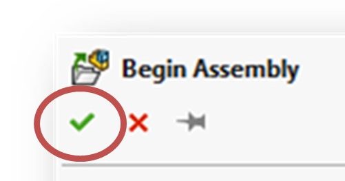
As we said previously, we always want to align the origin of the first (base) part with the origin of the assembly. To do this, click the Green Checkmark at the top-left hand side of the Begin Assembly dialog box.
Your first (base) part should now reside in the assembly document. Its origin should be aligned with the assembly origin. Note that the part will show up in the FeatureManager Design Tree. It will have an (f) before it, noting that it is fixed in position.
Okay, so we’ve got the first (base) part into the assembly. Now its time to bring in the other parts and “assemble” them together! There are two approaches here.
- You can bring in parts one at a time and mate them as you go, or
- You can bring in all the parts and then go about mating them
I think its less confusing to bring on parts one at a time and mate them as you go, so that’s what we’ll cover in this guide.
So, to insert your next component, click on the Insert Components icon in the Assembly CommandManager. The Insert Component PropertyManager will be displayed. From this dialog box you can browse for your component and insert it into the assembly.
Once you select the part for insertion by clicking the Open button, it will appear in the assembly window on the end of your cursor. You can place it anywhere by left-clicking your mouse. Try to place it close to where it will be when you actually assemble it, but don’t place it too close your base part. You’ll be able to move and rotate this part before you mate it to the base part. We talk about move and rotate next. Note that this second part will now show up in the FeatureManager Design Tree. It will have an (–) before it, noting that it is floating.
PLACING ADDITIONAL INSTANCES OF AN EXISTING COMPONENT IN THE ASSEMBLY (page 12-8)
Sometimes we need to place more than one instance of a component into an assembly. This is particularly true of fasteners. To do so:
- Press and hold the CTRL key
- Select the component in the FeatureManager Design Tree with the left mouse button
- Drag the cursor to a location in the assembly window where you wish to place the part
- Release the left mouse button to drop the part
- Repeat as many times as needed
NOTE: I’m going to go off script from the textbook a bit here. Now that you have a second part in the assembly, the next step would be to manipulate it into position so that you can apply the necessary assembly mates in order to assemble it to the base part. So, lets talk about moving and rotating your part next and then talk about mates:
MOVING INDIVIDUAL COMPONENTS (page 12-31)
Okay, so we’ve got a base part and a second part in the assembly document, but they’re in a random position and orientation relative to each other.
The workflow here is to get the second part into the assembly, then orient it so that it can be mated with the base part. This is no different than what you would do if you had a box full of parts in front of you and you had to glue them together. You’d have to “move” and/or ”rotate” one of the parts relative to the other to get them into the correct position for assembly. Note that a fixed part cannot be moved or rotated – only a floating part.
In this section, you’ll learn how to move a floating part to get it into position for mating. To do this, we use the Move Component command located on the Assembly CommandManager:
Click on the part in the assembly window you wish to move. Then click on the Move Component tool. To move the floating part you have to hold down the left mouse button while moving your mouse!
When you have the part in position, click the Green Checkmark at the top-left hand side of the Move Component PropertyManager.
ROTATING INDIVIDUAL COMPONENTS (page 12-32)
Rotating a part is similar to moving it. You can show the Rotate Component tool by clicking the down arrow under the Move Component tool icon. Click on the part in the assembly window you wish to move. Then click on the Rotate Component tool. Again, note that you have to hold down the left mouse button while moving your mouse to rotate a part. When you have the part in position, click the Green Checkmark at the top-left hand side of the Rotate Component PropertyManager.
NOTE: You can also move and/or rotate your part by “dragging”. This does not involve the use of the Move Component or Rotate Component tools. To do this, merely select the part and then use your mouse to either move or rotate the part. Hold the mouse button as follows:
-
-
- To Move – hold the LEFT mouse button down (see Page 12-31)
- To Rotate – hold the RIGHT mouse button down (see Page 12-32)
-
NOTE: You often have to alternate between moving and rotating a part multiple times in order to get it into the correct position for mating. This is an iterative process and can be a bit frustrating at times – just be patient. The idea is to get the component oriented so that it mates properly. This is similar to what you would do if you were actually assembling the parts in the real world.
We’re now going to back to the subject of Assembly Mates.
ASSEMBLING COMPONENTS (page 12-8)
Now that parts are placed into the assembly document, they now need to be assembled together. Just as with actual mechanical assembly, parts need to be constrained (degrees of freedom need to be reduced). In mechanical assembly, we would use fasteners, adhesive, welds, etc. to achieve this. In a model, we use mates.
Watch the video below to learn more about using mates to create assemblies:
In addition to limiting movement, mates help us to precisely place and position the component with respect to the other components in the assembly.
There are two methods for apply mates in Solidworks:
- The Mate PropertyManager
- Smart Mates
We use the Mate PropertyManager in this class so that’s what we’ll cover in this guide.
ASSEMBLING COMPONENTS USING THE MATE PROPERTYMANAGER (page 12-9)
Before we get going on how to do it, what the heck is a “mate” in Solidworks?? Well, a mate is a way to constrain a part relative to another. A mate reduces the degrees of freedom of the mated part – it restricts its ability to move and/or rotate.
There are three types of mates in Solidworks – Standard Mates, Advanced Mates and Smart Mates. We use Standard mates most of the time in this course along with an occasional Advanced mate. Smart Mates are an advanced topic.
There are several available types of “Standard” mates in Solidworks. They sound a bit like the relations we saw earlier.
Each specific mate is valid for a specific combination of part geometry. Tables exists which list the valid mates for different geometry types, but we typically don’t get that involved in this class as we keep the mates pretty simple.
Here are the basic Standard mates (see Pages 12-10 through 12-19):
Coincident – makes to coplanar faces coplanar. It basically “glues” one face of a part to another. We use this mate often. It is very robust and predictable, so it is a favored mate.
Concentric – aligns the central axis of one component with another. For example, we use this mate to align a cylindrical part when it is assembled into a hole. We use this mate often as putting fasteners (screws, bolts, rivets, pins, etc.) in holes is very common in assemblies.
Tangent – forces selected part geometry to be tangent. This mate is used frequently when you want to assemble a part to a sphere or the wall of a circular cylinder.
Parallel – forces selected part geometry to be parallel. Not used too often, but comes in handy.
Perpendicular – forces selected part geometry to be perpendicular. We don’t use this mate all that often.
Distance – applies a specified distance between the selected geometry of two parts. This mate is used where there is a required gap between two parts after they are assembled together. Not used too often. If a part can move between two points relative to another part, you need to use an Advanced mate for that situation.
NOTE: Often multiple mates are needed to adequately assemble two parts together and restrict their motions. Take a bolt being assembled in a hole. That application typically needs a concentric mate and a coincident mate, at a minimum. If we want to restrict the rotation of the bolt, additional mates would be needed as well.
Applying mates can be confusing and frustrating. It’s a learned skill that takes patience and practice. The more you do, they easier it gets.
So, lets get back to how to apply mates to an assembly…..
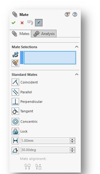
To apply mates using the Mate PropertyManager, choose the Mate command icon from the Assembly CommandManager. Note that the icon looks like a paperclip (how original!).
The Mate PropertyManager will be displayed (right and Figure 12-7, Page 12-10). Note that the Mate Selection rollout is activated (blue). You need to use the left mouse button to select a face (or less often an axis or a point) on the first component and an entity on the second component upon which to apply the mate.
NOTE: You will likely need to rotate your assembly when doing this in order to make the necessary entities visible for selection. You can rotate all the parts in the assembly by holding down the left mouse button and moving your mouse.
When selected, the entities will be highlighted in the assembly model and will appear in the Mate Selection rollout section.
NOTE: Note that when you are in the MATE tool and you select two parts to be mated, the system will access what you are trying to do and select a default mate type if it can. Be careful about just clicking the green check mark and accepting the default mate – make sure the mate the system selected is what you really want to apply.
Either select the default mate or one of your own. Then click the Green Checkmark at the top-left hand side of the Mate PropertyManager.
Keep applying mates until your parts are properly constrained. You can check for constraint after applying a mate by selecting the part and trying to move and/or rotate it. If it moves unexpectedly, you’ll need to apply additional mates to constrain it.
I repeat….applying mates can be confusing and frustrating. It’s a learned skill that takes patience and practice. The more you do, they easier it gets.
CONGRATULATIONS! YOU ARE DONE WITH CHAPTER 12!
