6 Creating Reference Geometries
CHAPTER 6 CREATING REFERENCE GEOMETRIES
This chapter is an extension of Chapters 4 and 5. It provides a deeper dive into the importance of sketching planes and introduces how to create what we call “reference geometries” – planes, axes, points. These reference geometries allow you to incorporate additional planes, in particular, that you can use while modeling. Remember that Solidworks only gives you the three principle planes – top, front and right – and sometimes that just isn’t enough to get the job done.
Additionally, in this chapter we further investigate the advanced options associated with the Extruded Boss/Base tool. These include “from”, “end condition”, and “direction of extrusion”. Knowing these options helps you use the Extruded Boss/Base tool. Sure, many times we just accept and use the default settings for these options, but there are times that you need to reach a little deeper and use a more advanced option.
Finally, we will also learn how to make cut features in our models using the Extruded Cut tool and the Revolved Cut tool. These tools really expand our modeling toolbox.
IMPORTANCE OF SKETCHING PLANES (page 6-2)
So far, all the models we’ve created have been done so by first sketching on a single plane and then extruding or revolving that sketch to create a base feature. The reality is that most designs are more complex than that and as such we need additional capabilities. Any of the three default planes provided – top, front or right – can be used to create a sketch on. Again this works great if all you want to do is add thickness to a 2D sketch. But designs are typically much more complicated than this and have features that cannot be created on the same plane as the base feature.
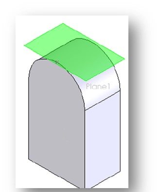
Once you have a base feature created, you can then select and use any planar surface as a sketching plane! We do this all the time. Looking at Figure 6-3 on Page 6-2 (and to the right), we can use any of the existing planar surfaces to activate as a sketch plane. These sketches can then be extruded (or cut, as the case may be) to create new features. Planar surfaces on these new features can then be used as sketch planes for even more features.
When we use a planar surface on a feature as a sketch plane to create new features, those new features typically are “welded” to the original feature. This provides for a model to be created with features that work in unison. This welding occurs by default.
CREATING REFERENCE GEOMETRIES (page 6-2)
“Reference geometries” allow you to incorporate planes, axes and points that you can use while modeling. Remember that Solidworks only gives you the three principle planes – top, front and right – and sometimes that just isn’t enough to get the job done. We narrow our discussion this semester to reference planes.
To create reference geometries, we use the Reference Geometry tool in the Features CommandManager. Once expanded, the flyout lists the various types of reference geometries that can be created with this tool. Pages 6-3 through 6-17 describe these various geometries and how to create them. I’m not going to cover all that again in this guide, but I will go over some important topics about creating reference Planes.
REFERENCE PLANES (page 6-3)
Watch the following YouTube video discussing how to create reference planes in Solidworks:
As we said before, generally speaking, nearly all designs that we model are multifeatured models (have more than one feature). And, most features are not created on the same plane as the original base feature. We need more sketch planes! So, one way to do that is to select one of the other 2 default planes provided by Solidworks. This is discussed in the section titled Default Planes (Page 6-3). Read this over.
If that doesn’t work out, we can turn to another method that was just discussed on Page 6-2. This option involves selecting a planar feature already on the model and using it as a sketch plane. Most of the time this works out and we can create all the features we need to create. This is preferred over creating new planes.
A third method is to create a totally new plane that can be used as a sketching plane. This would be a reference Plane and is discussed in the next section. Reference planes are typically created when the plane you need to sketch on is at an offset distance from a plane or a planar face. Another situation where a reference plane may be needed is when you need a sketch plane that is tangent to a cylindrical face of a shaft.
CREATING NEW PLANES (page 6-4)
If we need to create a new reference plane, we invoke the Reference Geometry tool in the Features CommandManager and select the Plane option from the flyout (Figure 6-4, Page 6-3)
Once the Plane option is selected, the Plane PropertyManager will be displayed (Figure 6-5, Page 6-4 and to the left). I need to be honest here that using this tool can be very confusing! Make sure you read the next several pages and look over the examples provided.
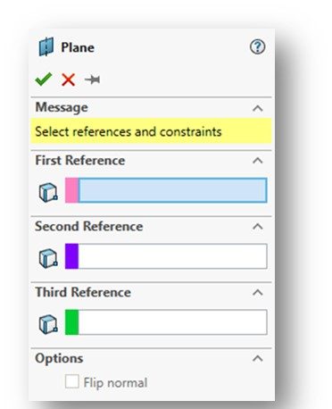
You really have to think through how this new plane is going to be defined. This is accomplished by stating what the “references” are that define and constrain it. These references are typically default planes and/or planar surfaces on the model. The Plane PropertyManager provides the ability to select “First”, “Second” and “Third” references. Not all reference planes require all three references. When the tool is invoked, the Fist Reference input will be automatically activated – you will see that the rollout box will be highlighted in blue – and it is ready for you to select the plane or planar surface you wish to use.
CREATING A PLANE AT AN OFFSET FROM AN EXISTING PLANE OR A PLANAR FACE (page 6-5)
This is a typical reference plane that we use fairly frequently. This type of plane would be parallel to the existing plane or planar surface but at a define offsetting distance.
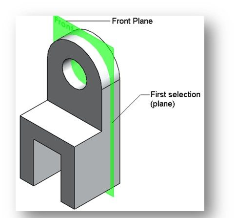
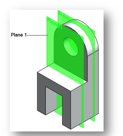
The First Reference for this type of plane is often one of the 3 default planes – top, front, right. The example above (Figure 6-6 and 6-7, Page 6-5) illustrates this. Once you define the First Reference, some constraints will be displayed in the First Reference rollout. These constraints include:
- Offset Distance button (chosen by default)
- Flip Offset check box
- Number of Planes to Create spinner
CREATING A PLANE PARALLEL TO AN EXISTING PLANE OR PLANAR FACE AND PASSING THROUGH A POINT (page 6-5).
Similar to a plane with a defined offset distance. Just read over.
CREATING A PLANE AT AN ANGLE TO AN EXISTING PLANE OR A PLANAR FACE (page 6-6)
Just read over. Unlikely we will use this option this semester.
CREATING A PLANE PASSING THROUGH LINES/POINTS (page 6-7)
Just read over. Unlikely we will use this option this semester.
CREATING A PLANE NORMAL TO A CURVE (page 6-8)
Just read over. Unlikely we will use this option this semester.
CREATING A PLANE ON A NON-PLANAR SURFACE (page 6-9)
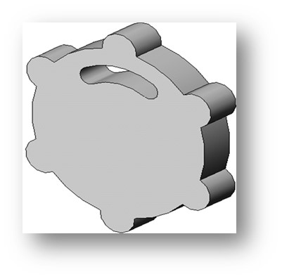
This is the option we use to create a plane tangent to a cylindrical surface. This does come up occasionally. For example, take a look at Figure 6-18 on Page 6-9 (and shown to the right). If we needed to drill a hole into the top of this part tangent to the arc and parallel to its vertical sides, we would need a plane as shown to sketch our hole on. It is not possible to sketch a hole tangent to this arc without the aid of this reference plane. This sketched circle could then be cut into the part per the Extruded Cut tool described later in this chapter.
Read this section over. You may need to use this option this semester.
CREATING A PLANE IN THE MIDDEL OF TWO FACES/PLANES (page 6-9)
We don’t use this semester. Unlikely we will use this option this semester.
CREATING REFERENCE AXES (page 6-10)
Just read over. Unlikely we will use this option this semester.
CREATING REFERENCE POINTS (page 6-13)
Just read over. Unlikely we will use this option this semester.
CREATING REFERENCE COORDINATE SYSTEMS (page 6-16)
Just read over. Unlikely we will use this option this semester.
CREATING CENTER OF MASS (page 6-16)
Just read over. Unlikely we will use this option this semester.
CREATING A BOUNDING BOX (page 6-17)
Just read over. Unlikely we will use this option this semester.
ADVANCED BOSS/BASE OPTIONS (page 6-18)
- Using planar surfaces on a feature as a sketch plane
- Use of “End Conditions” when creating features to capture design intent (“Blind” vis. “Up to Next” when Extrude-Cutting a hole used as an example)
- Deleting a feature
- Editing the sketch used to create a feature
- Editing a feature
- What does “Merge Result” mean when creating a feature?
The Extruded Boss/Base tool is the most frequently used of the FEATURES tools. Initially, it is employed to add thickness to a 2D sketch, thus creating a 3D base feature. Think of it as a digital 3D printer, building a part up from a base. This was discussed in Chapter 5.
The beginning of this section rehashes base feature creation, using the Extruded Boss/Base tool, discussed from Chapter 5. IT then goes into the various more advanced options available with this tool. Don’t confuse this tool with the EXTRUDED CUT tool covered later in this chapter. You cannot make a cut (ie., a hole in a part) using the Extruded Boss/Base tool!
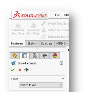
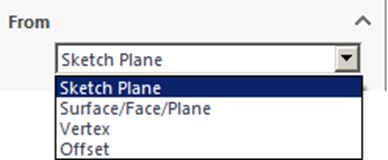
EXTRUDED BOSS/BASE “FROM” ROLLOUT (page 6-18)
Extrusion have to start “from” somewhere. The From rollout found in the Boss Extrude PropertyManager is used to tell the system where you want the extrusion to start from.
Extruded Boss/Base “FROM” Roll-Out Options
There are several options here, which are displayed in the drop-down list:
- Sketch Plane
- Surface/Face/Plane
- Vertex
- Offset
Sketch Plane is the default selection and is frequently used. It assumes that the extruded feature will start from the plane the sketch was drawn on (see figure below). This is the option we use most frequently. Just read over the discussion of the other options.
END CONDITION (page 6-20)
Just as an extrusion has a definitive starting point (the “From” condition), it must also have an ending point – Solidworks terms this the “End Condition”. The End Condition is defined in the Extrude Boss PropertyManager.
Pay attention to the entry box under Direction 1 (see below).
This is where you define the “end condition” of the extrusion. There are a few options available:
- Blind
- Through All
- Up to Vertex
- Up to Surface
- Offset from Surface
- Up to Body, and
- Mid-Plane.
“Blind” is the default end condition. The Blind option always requires an extrusion value to be entered. It also only extrudes in a single direction a specified distance. Although we use this option frequently, it is not discussed in the textbook for some unknown reason.
The other end condition option we use a lot is “Mid-Plane”. This option extrudes an equal amount in two opposite directions. This is a good choice if the “design intent” of the part would required that a part be symmetrically extruded about a plane or surface, rather than in a single direction.
Make sure you read the discussion on the other End Conditions. Don’t just always accept the default end condition. It may not reflect the desired design intent.
NOTE: Depending upon what precision values is set for “length” dimensions in your UNITS command, the model may display a lower precision value (fewer digits to the right of the decimal point). However, the actual value taken on by the model is what you enter, not the displayed value.
Another thing about the display of extrusion distances is that they will never be black on your model. These are called “applied dimensions” and are not Smart Dimensioned. Thus, they do not “define out” like the dimensions you Smart Dimension.
DIRECTION OF EXTRUSION (page 6-25)
Note that there is a Direction button in the Extruded Boss Property Manager (see below):

We didn’t really talk about this when this tool was introduced back in Chapter 5 because we just simply extruded a sketch up from the sketch plane it was drawn on by just accepting the default entries.
The reality is that you can extrude “up” or “down” – the direction can be toggled by clicking on the arrow to the left of the Direction 1 rollout.
MODELING USING THE CONTOUR SELECTION METHOD (page 6-25)
The Contour Selection Method is a very useful functionality in Solidworks which allows you to select parts of a sketch to create features. Complex sketches sometimes cannot be extruded, for example, because the software cannot figure out what you are try to do. Contour Selection lets you select what sketch features to create into a feature. Use this as your fall-back position when you just can’t get that sketch to extrude (or cut) properly.
Figures 6-64 through 6-67 on Page 6-26 do a great job of illustrating how this works to extrude only part of a sketch.
CREATING CUT FEATURES (page 6-28)
Cut Extrude and Revolve Cut are material removal processes – similar to what we do when we drill a hole in a part, cut a slot in a part with a milling machine, or remove material with a lathe. A cut can only be effected if a base feature exists first.
Watch the following YouTube video which illustrates how to sketch on the planar surface of an existing feature and how to use the Cut-Extrude tool:
CREATING EXTRUDED CUTS (page 6-29)
Before you can do a cut using the Extruded Cut tool, you must first create a sketch that will be used to make the cut. Once the sketch is created, choose the Extruded Cut tool from the Features CommandManager.
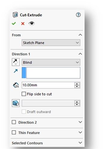
The Cut-Extrude PropertyManager (Figure 6-74, Page 6-29 and below) will be displayed. It is noted that many of the options in this PropertyManager look very similar to those in the Extruded Boss Property Manager previously discussed. This is because the two tools function very similarly.
I’m not going to go through all of the various options associated with this tool. They are described on Pages 6-29 through 6-32.
As with the Extrude Boss/Base tool, pay particular attention to the options for the End Condition of the cut discussed on Page 6-30.
CREATING MULTIPLE BODIES IN THE CUT FEATURE (page 6-32)
It is unlikely we will use this functionality this semester. Just read it over – it is pretty cool.
CREATING REVOLVED CUTS (page 6-34)
It is unlikely we will use this functionality this semester. Just read it over.
CONGRATLUATIONS! You are done with Chapter 6!
