4 Adding Relations and Dimensions to Sketches
CHAPTER 4 ADDING RELATIONS & DIMENSIONS TO SKETCHES
This chapter is really important. It introduces adding dimensions and geometric relations to sketches. The end-game here is to wind up with a “fully defined” sketch – a sketch in which all of the entities of the sketch and their positions are completely defined by a dimension or a geometric relation. All of the degrees of freedom in such a sketch are constrained such that the sketched entities cannot move or change their size or location unexpectedly. We always strive to build models based on fully defined sketches. This is not something we talk about in a 2D CAD system such as AutoCAD.
For a demonstration about defining your sketches, see the video below:
APPLYING GEOMETRIC RELATIONS TO SKETCHES (page 4-2)
Geometric relations, or “relations” for short, were briefly discussed back in Chapter 1. They are applied to sketch entities to capture the “design intent” (also discussed in Chapter 1). They also constrain the degrees of freedom of the sketched entities, thus helping to define them. Relations are automatically applied as you sketch (ie., when you create a rectangle, 2 opposite sides are automatically assigned vertical relations and the other 2 opposite sites are assigned horizontal relations). You can also manually add (or delete) relations as needed using the Add Relations PropertyManager.
APPLYING RELATIONS USING THE ADD RELATIONS PROPERTYMANAGER (page 4-2)
The Add Relations PropertyManager is used to manually add relations. It can be selected by clicking on the Display/Delete Relations icon on the Sketch tab of the CommandManager:
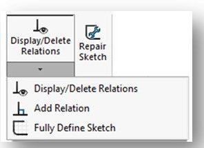
If you click on the Add Relation option, the Add Relations PropertyManager will be displayed:
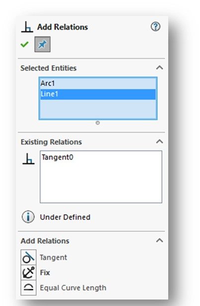
Once the Add Relations PropertyManager appears, you can apply a relation to a single entity or between two or more entities in a sketch (ie., a line tangent to a circle). Note that once you select the entity (or entities you wish to apply relations to), Solidworks will display those relations it thinks you can apply in the Add Relations rollout. The most appropriate relation appears in bold letters. The Existing Relations rollout will show what, if any, relations already exist.
Similarly, you can start to add relations without going through the Display/Delete Relations icon on the Sketch tab. If you select an entity and then hold the CRTL key and select a second entity, the Add Relations PropertyManager will be presented. The Existing Relations rollout will show what, if any, relations already exist between the entities. The Add Relations rollout will show which ones can be added.
I recommend you look over the various relations and their descriptions depicted on Pages 4-3 through 4-7. The most commonly used relations are:
- Horizontal
- Vertical
- Perpendicular
- Parallel
- Tangent
- Concentric
- Coincident
Make sure you can recognize the symbols for at least these relations. When applied (either automatically or manually), their symbols will appear on your sketch.
There is more about displaying and deleting relations later in this chapter starting on Page 4-35.
AUTOMATIC RELATIONS (page 4-7)
Automatic relations applied automatically to a sketch while you are drawing. This capable can be turned off, but that is never recommended. Solidworks does a very good job of applying the correct relations. If it does apply a relation you find that you don’t need, you can always delete that specific relation at any time.
The following 8 relations can be added automatically:
- Horizontal
- Vertical
- Perpendicular
- Tangent
- Coincident
- Midpoint
- Intersection
- Cordial
If your sketch gets too cluttered, you can turn off the visibility of your relations by using the Hide/Show Items command in the View (Heads Up) Toolbar – the command icon looks like an “eyeball” (see below):

Then click View Sketch Relations Tool (it looks like the perpendicular relation symbol). The View Sketch Relations tool acts like a toggle switch -if you can’t see your relations while you are sketching (and want to), you can also make them visible through the Hide/Show Items command.
DESIGN INTENT (page 4-8)
As we’ve discussed before, design intent is a very important component of parametric solid modeling. What does it mean? When you create a part, it should be created in such a way that if any change is made to it in the future, the change should affect the design without impacting the function of the part. How do we do this? Design intent is implemented by applying proper constraints – geometric relations and dimensions.
Capturing the design intent results in a robust, an easy-to-edit model.
Look over the examples provided in Figures 4-7 through 4-10 (pages 4-8 and 4-9). They show how dimensions can be used to capture design intent.
What these examples illustrate is that the dimensions we apply to model have consequences. We may not see them at the onset of modeling, but later on we will see the consequences when we attempt to edit the model. In industry, there are many examples of where a company wound up having to completely re-model a part after attempting to edit the original model because the design intent was not properly captured in the original model. This is not time or cost effective.
When you model parts in industry, you typically know how they are going to be used in the next higher assembly – therefore, you know the design intent. However, in the types of exercises we do in a class like ours, it can be very difficult to know what the design intent really is. Often, we have no idea how the parts we are modeling are actually used. On some exams I will tell you what the design intent needs to be and you’ll have to model accordingly.
Bottom line – put your brain in gear before just throwing a bunch of dimensions or relations on to a model.
DIMENSIONING A SKETCH (page 4-9)
This is a very important section!
Up to this point, we have not been applying any dimensions to our sketches. That’s going to change! And in one respect our life will get easier. Using dimensions actually makes modeling easier. The way we’ve modeled in the first 3 chapters has been quite “clunky”, to say the least. Using the Smart Dimension tool will change all that (for the better!).
One thing to point out right away is that the dimensions we apply to sketches are not the same dimensions that you apply in a drawing. We’ll talk about dimensioning drawings in Chapter 14. The dimensions we apply to a sketch actually create the model and become part of the parametric database of information that gets created when the model is produced. Parametric modeling programs, like Solidworks, “borrow” these dimensions from the model to help us accurately apply dimensions in the drawings that we create from the models themselves. If you think back to dimensioning a drawing in a program like AutoCAD, we created every dimension as we constructed the drawing and those dimensions were actually just “annotations”, or notes – they were not closely associated with the entity on the sketch we were applying them to. For example, there is nothing to stop a draftsperson from applying a dimension to an entity in AutoCAD that does not actually reflect the size of that entity (ie., a line of length 1.25 inches is dimensioned as 1.26 inches). In contrast, in Solidworks the dimensions we “borrow” from the model to create the drawing are the actual sizes of the entities in the model. That’s why drawings are really just an afterthought in Solidworks – the model is everything!
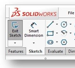
How do we apply dimensions to our sketch? We use the Smart Dimension tool which is available in the Sketch CommandManager.
By the way, when we dimension drawings later in the semester, we will find that there is also a Smart Dimension tool that operates nearly identically to the one we use at the sketch level.
All of you have had experience apply dimensions. The routines in Solidworks are very similar to those found in programs like AutoCAD. Therefore, I’m not going to spend time in this guide to cover those. But I do want to point out one thing here – we do not have to meet ANSI dimensioning requirements when we dimension our sketch. Although its good to keep them in mind, we don’t have to be nearly as particular about the placement of dimensions on a sketch as we do when we are dimensioning an actual drawing. The placement of dimensions on a sketch does not directly dictate how they will appear on the drawing – therefore we could consider the sketch dimensions more like “working” dimensions. The main focus at the sketch level is to apply dimensions such that the sketch fully define and reflects the desired design intent. Its not about making the sketch “look pretty” or meet ANSI dimensioning requirements.
CONCEPT OF A FULLY DEFINED SKETCH (page 4-30)
We already talked a little about what a “fully defined” sketch means. Once you create a sketch, you must apply the relations and dimensions (Smart Dimensions) needed to constrain the entities relative to their surroundings.
NOTE: It is very important to point here that it is critical that your sketch be tied to the ORIGIN. We do this by ensuring at least one of the entities either starts at the origin (ie., one end of a line, one corner of a rectangle, or the center of a circle or polygon). While it is possible to dimension a sketch entity back the origin, it is far more desirable to “start the sketch” at the origin in the first place. If your sketch is not tied to the origin, it will not fully define.
I don’t want to minimize how difficult it can be to get a sketch to fully define, particularly a complicated sketch. Sometimes you just can’t get a sketch to fully define no matter what you do. There’s a limit on how much time and energy I can expect you to expend in this endeavor. Here’s a list of the 7 things I would expect:
- Your sketch starts at the origin
- The centers of all circles are dimensioned in X and Y from the origin or a defined entity on the sketch
- The length of all lines have been Smart Dimensioned
- The diameters of all circles have been Smart Dimensioned
- All angles are Smart Dimensioned (a few different ways to do that as you know)
- The radius of all arcs are Smart Dimensioned
- All chamfers are Smart Dimensioned (a few different ways to do that as you know)
When we have a test, I’ll typically do my best to give you parts to model that I believe you have a reasonable chance of getting to fully define. All I ask is that you do your best by at least doing the 7 things listed above. There’s no reason not to.
The “state” of your sketch will be identified in the lower right-hand side of the notification bar at the bottom of the screen. You can also determine the state by looking at the color of the sketch entities (see below).
FULLY DEFINED (page 4-30)
In a fully defined sketch, geometric relations and Smart Dimensions are used to fully constrain all the sketch entities. The sketch entities cannot move or change size or location unexpectedly – in essence, they are “locked in place”.
When a sketch is fully defined, all its entities will appear in BLACK. Getting all your entities to turn black is your goal here.
Watch the YouTube video below to learn more about a fully defined sketch:
There are 5 “states” that a sketch can be in besides fully defined. They are described in the sections that follow. I’ll cover a couple of them:
OVERDEFINED (page 4-30)
Your sketch can be in the overdefined state if some of the dimensions , relations, or both are in conflict or there are too many of them. This state typically occurs when you place too many (sometimes redundant) Smart Dimensions on your sketch. Try to avoid just throwing a bunch of dimensions on a sketch without thinking about what you are doing. Go easy when dimensioning – don’t just keep throwing more and dimensions on the sketch hoping it will define.
NOTE: The same old adage of dimensioning we learn when we dimension drawings applies when Smart Dimensioning a sketch: don’t dimension something twice!
When a sketch is overdefined, one or more of its entities will appear in YELLOW.
When any of your entities turn yellow, it is time to STOP! You need to determine which dimension (or relation) is creating the conflict. Often times it is the last one you applied. To correct an overdefined state, you need to delete the extra or conflicting dimensions or relations. How to do that is covered later in this chapter.
UNDERDEFINED (page 4-30)
Your sketches will spend a lot of time in the underdefined state. That’s because we often wind up with underdefined sketch entities as we model. Underdefined sketches have at least one entity that is not fully constrained and require the application of more relations and/or Smart Dimensions.
When a sketch is underdefined, one or more of its entities will appear in BLUE.
DELETING OVERDEFINED DIMENSIONS (page 4-32)
When you add a dimension that overdefines a sketch, you will get the dreaded Make Dimension Driven? Message (see below). This message indicates that if you add this dimension the sketch will be overdefined or the sketch cannot be solved.
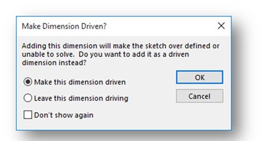
In addition, you’ll see the color of the affected entities change to YELLOW.
The textbook goes through a very detailed routine involving using the SketchXpert Property Manager to “fix” the situation automatically.
NOTE: Here’s a word of advice – if you get this dialog box, just click the “CANCEL” button and rethink what you are doing. Do you really need to add that dimension? Typically, you don’t because there are already enough dimensions on the sketch to constrain everything. Manually resolve your overdefinition issues.
Figure 4-53 is a good example of this. Do you really need to add the 100mm dimension on the right-side vertical line? Look at the dimensions you already have on the sketch and the geometric relations. Is there really any need for that additional 100mm dimension? Nope! If the top and bottom lines are both horizontal, and the right-hand vertical line is 100mm, and the right and left lines are both vertical, the right-hand side vertical line has to already be 100mm long!
DISPLAYING AND DELETING RELATIONS (page 4-35)
If a sketch is overdefined after adding dimensions and relations, you will need to delete some of the overdefining, dangling, or unsolved relations and/or dimensions. Also, sometimes Solidworks will automatically add a relation while you are sketching that you really didn’t want that interferes with how you want the sketch to behave. An example of this is when you place a line and a circle coincident to each other on a sketch (even though you don’t want them to be constrained as tangent) and Solidworks thinks you want them to have a tangent relation. But what if later on you need to modify that sketch and the tangent constraint won’t let you make the necessary modification? Well, you’ll need to delete that unwanted tangent relation.
The textbook goes through a very detailed explanation of how to use the Display/Delete Relations Property Manager to delete relations in your sketch. The reality is, you seldom need to do it this way. Our sketches are pretty simple, so you normally know exactly what relation you want to delete. Given that, you can simply left-click on the offending relation and then select the Delete option from the fly-out menu that appears. Its that simple. The discussion in the book is way more complicated than we need.
OPENING AN EXISTING FILE (page 4-39)
By this point, I think everyone already knows how to open up an existing file in Solidworks. You can read through this section, but just note it for later reference if needed.
I will take this opportunity to remind you to always save your files in a folder location that you can easily find. You should have already set up a dedicated folder for this class in your My Documents folder on the network. This folder is accessible from any networked computer on campus and also remotely via CITRIX. Within that folder, I recommend that you create a folder for each chapter’s assignments. Don’t just intermix all your files for this class with all your files from every other class!
Just another note – Solidworks doesn’t “eat” any files. I hear students say that often. Most of the time they just can’t find them – normally because they didn’t set up and use the folders as I just outlined.
Also, make sure you name your files correctly when saving. I typically tell you what file naming convention to use in the assignment. Not following it screws up the assignment download and grading process. And, always do a FILE > SAVE AS when saving your files to ensure they wind up the folder you want them in!
CONGRATULATIONS! You are done with Chapter 4!
