5 Advanced Dimensioning Techniques and Base Feature Options
CHAPTER 5 ADVANCED DIMENSIONING TECHNIQUES & BASE FEATURE OPTIONS
This chapter is an extension of Chapter 4. We’ll be learning some tools associated with creating “base features” (3D models). How to manipulate your model while working on it is also covered. We will also learn how to apply a material to a model so that it takes on the properties of that material. This will allow us to easily find the mass, surface area, center of gravity, etc. of our part. We start out the chapter by doing more work on fully defining sketches, which is always fun!
ADVANCED DIMENSIONING TECHNIQUES (page 5-2)
In this chapter, some advanced techniques for applying the dimensions necessary to fully define our sketches are discussed. One such tool is the Fully Define Sketch tool.
FULLY DEFINING THE SKETCHES (page 5-2)
The Fully Define Sketch tool is used to apply relations and dimensions to a sketch automatically. It can be accessed from the Display/Delete Relations command icon located in the Sketch CommanManager:
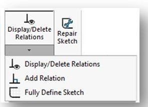
You can also access this tool by clicking on and expanding the Tools menu tab in the Solidworks Menu at the top of the screen (see right). You then select the Dimensions option from the drop-down list of options.
NOTE: To be honest, I don’t use this tool as my primary way of defining my sketches. I manually go through and apply the relations and Smart Dimensions I need as we described in Chapter 4 until I get my sketch to fully define. “Automatic” tools like this one can get you into trouble in a big hurry if you’re not careful! I like to be in full control of what happens on my sketch.
So, here’s how I do use this tool. As sketches become more and more complicated, it gets pretty hard sometimes to get every entity in a sketch to define. Sometimes, people just keep adding more and more dimensions to their sketch when this happens, hoping beyond hope that they’ll get lucky and stumble upon the right dimension to get those last couple of entities to fully define. Of course, as we discussed in Chapter 4 this type of approach can lead to overdefinition – which itself is just as bad (and sometimes worse) than underdefinition. So, what do you do??
Well, you can turn to the Fully Define Sketch tool to help get those stragglers to define. By just selecting the problem entities (see section ENTITIES TO DEFINE), you can let Solidworks attempt to use its power to get the sketch to fully define. I use it as a “tool of last resort”, per se.
NOTE: Just a word of caution here – this doesn’t always work. Sometimes due to the relations and Smart Dimensions you’ve already applied to the sketch, the Fully Define Sketch tool can’t figure it out. If that happens, its probably time to just give up and move on. The world will not stop spinning if you leave an entity or two undefined in your sketch. That doesn’t mean to just leave everything undefined – there’s typically a lot of entities that will define pretty easily.
So, look over the information on Pages 5-2 through 5-4, paying the most attention to the section titled ENTITIES TO FULLY DEFINE (page 5-2).
DIMENSIONING THE TRUE LENGTH OF AN ARC (page 5-4)
We don’t use this capability in this class.
MEASURING DISTANCES AND VIEWING SECTION PROPERTIES (page 5-5)
We don’t use the capabilities in this section (pages 5-5 through 5-8) in this class. These measurement are associated with the sketch. Finding these measurements at the sketch level usually isn’t particularly helpful. We focus more on measurement associated with 3D model – and will cover that later.
CREATING BASE FEATURES BY EXTRUDING SKETCHES (page 5-9)
This section is very important!!
This is where we turn the corner from 2D sketches to 3D models. In this section we learn how to covert our sketches into 3D “base features” by extruding the sketch. This is by far the most commonly used technique for creating solid models.
Extrusion is done using the Extruded Boss/Base tool from the Features CommandManager. Note that you must first click on the Features tab to invoke the Features CommandManager:
Once you click on the Extruded Boss/Base command icon, the sketching environment will close – you are no longer sketching, you are modeling. The part modeling environment will open.
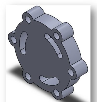
Two different types of extruded features can be created – “solid” or “thin”. Which one is created depends upon the attributes of the sketch you are attempting to extrude and the options you select while doing the extrusion. The difference between these two types is described over the next several pages of the text. The vast majority of what we create are “solid” features (see below):
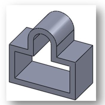
In contrast, here’s what a “thin” feature looks like:
CREATING SOLID EXTRUDED FEATURES (page 5-9)
You can create a solid feature after you have completed a closed 2D sketch. Solidworks is going to give you heartburn if you attempt to extrude a sketch that is not closed. So, you need to be careful when you sketch – make sure your lines are “end-to-end”.
Repeating from the previous section, extrusion is done using the Extruded Boss/Base tool from the Features CommandManager. To make the Features CommandManager visible, you need to click the Features tab first which will exit you from the sketching environment.
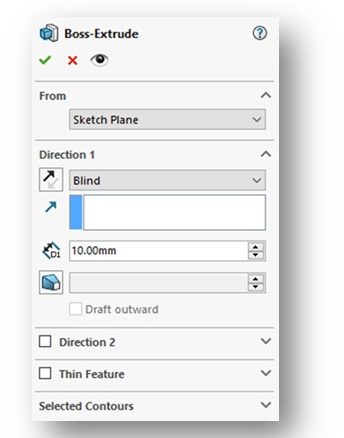
Once you click on the Extruded Boss/Base tool, the Boss-Extrude PropertyManager will appear (see below and also Figure 5-9, Page 5-9).
Also, the view of your sketch will change to trimetric (a view similar to isometric) so that you can see the effect of extrusion in 3D – its mush easier that way. Solidworks will provide a preview of what the extruded model will look like based on what it thinks you are trying to accomplish – of course, its not always correct so pay attention.
A preview of an extrusion is shown below (and as Figure 5-11 on Page 5-10):
Note that you can still see the outline created by your 2D sketch. The arrow indicates which way Solidworks has proposed the extrusion be done. Again, its only a proposed extrusion – you can change the direction in the Boss-Extrude PropertyManager. Don’t just click the green checkmark without looking and thinking about what you are doing!!
Another thing to notice is that if your closed sketch contains some closed “inner loops” (like a circle in the above example), those loops will not be extruded – they will be “subtracted”, resulting in voids in your 3D model. That’s how Solidworks interprets these inner loops. This points out an important point – you need to be careful about what goes on your sketch!
The information about each of the options in the Boss-Extrude PropertyManager are found on Pages 5-9 through 5-14. These are very important and should be read over carefully.
At the bottom of the Boss-Extrude PropertyManager is an option called Selected Contours. This is not covered in the text, but is very useful. This option allows you to manually select the areas of your sketch to extrude rather than letting Solidworks kind of pick-and-chose. Keep this option in mind as we do use it occasionally.
It should be noted that we don’t use the Extruded Boss/Base tool to create cuts, holes, slots or other voids in a model. For that we use another tool – the Extruded Cut tool. This tool is used to cut into a 3D model after it is produced. This is covered in Chapter 6.
Watch the following YouTube video providing a very detailed overview of using the Extruded Base/Boss tool in Solidworks. It covers many of the options in the Boss-Extrude PropertyManager:
CREATING BASE FEATURES BY REVOLVING SKETCHES (page 5-14)
In addition to extrusion, you can also create a 3D base feature by revolving a sketch about an axis using the Revolved Boss/Base tool. Like the Extruded Boss/Base tool, the Revolved Boss/Base tool is found on the Features CommandManager. To make the Features CommandManager visible, you need to click the Features tab first which will exit you from the sketching environment.
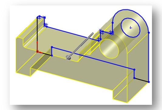
In order to revolve, your sketch must be complete and must be a “closed” figure. Once the Revolved Boss/Base tool is invoked, the Revolve PropertyManager will be displayed (Figure 5-22, Page 5-15).
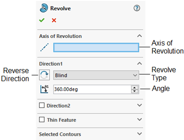
In order to revolve, you must have an “axis of revolution” ready to go before you invoke the Revolved Boss/Base tool. The revolution axis could be an axis (a “centerline” line type) inserted into the sketch, an entity of the sketch being revolved, or the edge of another feature. Most of the time it’s a centerline being used as an axis of revolution. If you’ve included a centerline in your sketch, Solidworks should notice it and automatically use it as the default axis of revolution. If you are using something other than a centerline, once in the Revolve PropertyManager, you will need to tell Solidworks what to use as your axis of revolution by clicking in the Axis of Revolution option and then select your axis from your sketch.
The information about each of the options in the Revolve PropertyManager are found on Pages 5-15 through 5-18. These are very important and should be read over carefully. It is noted here that we don’t do too many revolves in this class.
DETERMINING THE MASS PROPERITES OF PARTS (page 5-18)
Because Solidworks is parametric, it is quite easy for the software to crank out the calculations necessary to find mass properties of the model – density, mass, volume, surface area, center of mass, principle axis of inertia, principle moment of inertia, and moments of inertia. We are generally interested in the properties of mass, volume, and surface area. Doing these calculations manually can be quite daunting, time consuming and error-prone.
Although the book doesn’t say it here, you really need to apply a material to the model before attempting to determine any mass properties. This is discussed later starting on page 5-27. Solidworks has a very robust database of materials that you can apply – steels, aluminum alloys, copper alloys, plastics, wood, etc. Once the material is applied, your model takes on all of the physical properties of the assigned materials, including density, tensile strength, etc. For this reason, we can find the mass of the model quite easily and also run strength analyses/simulations to see how our part handles stresses that may be applied in use.
Watch the video below for a detailed discussion of applying material to a model and determining mass properties:
Also, review the attached document detailing on how to apply material to your model and then how to determine mass properties:
PROCESS FOR APPLYING MATERIAL TO A MODEL IN SOLIDWORKS
This document can also be found in the Course Documents folder of BlackBoard.
Also, visit the web page shown below to learn more about mass properties in Solidworks:
Exploring Mass Properties in SOLIDWORKS (hawkridgesys.com)
DYNAMICALLY ROTATING THE VIEW OF A MODEL (page 5-19)
Unlike sketching, when we create 3D models we need to be able to dynamically rotate the model. This is because these models have multiple faces and we often need to perform additional feature-based work on one or more of those faces after the initial base feature is created. For example, we may need to bore a hole in the side of a block.
The most efficient way to rotate a model dynamically (while working on the model) is to press and hold the center mouse button/wheel. When you then move the mouse, the model will dynamically rotate in space. This method should work just fine when you are working remotely from home.
NOTE: In the fall of 2020, we had an issue with rotating models when students worked on the CITRIX-based computers on campus. You will need to use the alternate method described in the book on Page 5-19: View > Modify > Rotate.
Practice rotating your model and get good at it.
Watch the YouTube video below to gain a better understanding of how to manipulate your model:
ROTATING THE VIEW AROUND A SELECTED VERTEX, EDGE, OR FACE (page 5-19)
We don’t use this capability in this class.
MODIFYING THE VIEW ORIENTATION (page 5-20)
There are several predefined standard views in Solidworks that also can be used to help you view your model as it is being created. These views can be accessed by selecting the View Orientation selection (cube with two arrows pointing to surfaces on it) from the View (Heads–Up) toolbar located at the top of the drawing window:

Click the down-arrow and the select the View Orientation option. The flyout below will be displayed (see below and also Figure 5-32, Page 5-20):
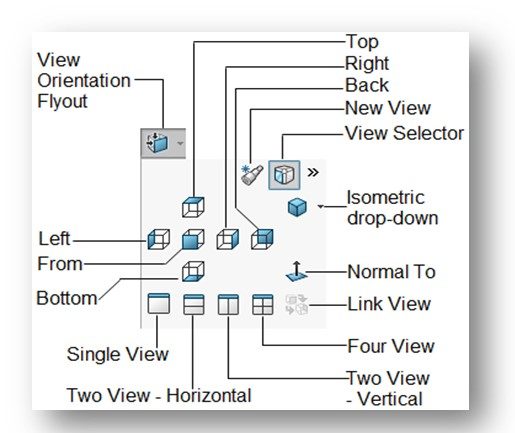
Your model will be immediately be displayed inside what Solidworks calls the “View Selector” (see below and Figure 5-33, Page 5-20). Basically, it pits a “glass box” around your part that is interactive. You can select on of the 6 standard (“principle”) views and also isometric by clicking on the appropriate face of the glass box.
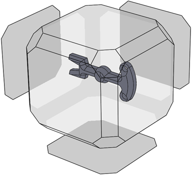
You can also select any of the 6 standard views or isometric orientation from the View Orientation flyout (above).
We don’t create unique user views or modify any of the standard views in this class. We also don’t use the triad to change the orientation of the model.
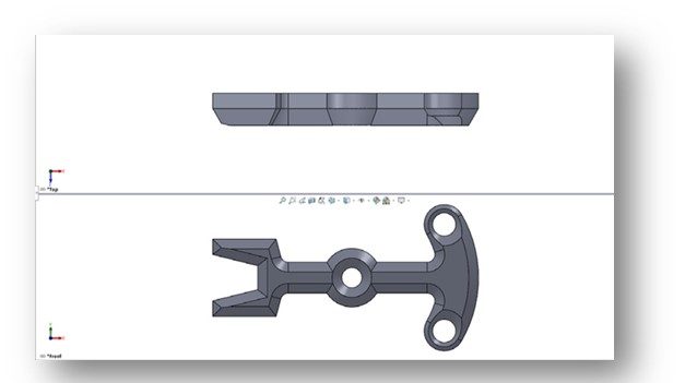
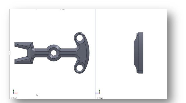
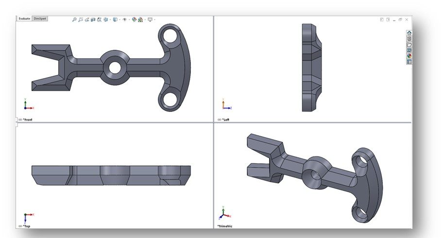
DISPLAYING THE DRAWING AREA IN VIEWPORTS (page 5-22)
“Viewports” are like windows into your model. Most of the time, we work with a single viewport – the drawing area is just one big window pane. But, Solidworks allows us to view our model in multiple viewports (up to 4) at the same time. The viewports can basically display whichever of the 6 principle views you wish. When you click in a viewport to make it active, it will have its own View (Heads-Up) toolbar, thus you can change what view is displayed in that viewport. I normally set them for top, front, right-side and isometric (like a standard three-view orthographic drawing). I don’t use this feature too often, but I do use it to see how my model will look in a future drawing.
Viewports can be accessed through the View Orientation flyout discussed earlier in this chapter (See Figure 5-32, Page 5-20).
The model is “hot” in each of the viewports, meaning that it can be rotated, zoomed, and even modified while that viewport is active. The other viewports will dynamically update when you are working in another viewport.
Watch the following instructor video demonstrating how to use viewports in Solidworks:
DISPLAY MODES OF A MODEL (page 5-24)
Solidworks provides various predefined display modes for you to use to display your model. These modes are accessible through the Display Styles flyout located from the Display Style icon (half-colored cube) in the View (Heads-Up) toolbar:

The available display styles are:
- Wireframe (we don’t use in this class)
- Hidden Lines Visible (we occasionally use in a drawing view)
- Hidden Lines Removed (sometimes use in a section view)
- Shaded with Edges (we use this style frequently)
- Shaded (don’t really use)
ADDITIONAL DISPLAY MODES (page 5-25)
We don’t use Shadows in Shaded Mode or Perspective display modes inthis class.
ASSIGNING MATERIALS AND TEXTURES TO MODELS (page 5-28)
Assigning Materials is Very Important!
As stated earlier in this guide, Solidworks has a very robust database of materials that you can apply – steels, aluminum alloys, copper alloys, plastics, wood, etc. Once the material is applied, your model takes on all of the physical properties of the assigned materials, including density, tensile strength, Modulus of Elasticity, etc. For this reason, we can find the mass of the model quite easily and also run strength analyses/simulations to see how our part handles stresses that may be applied in use.
Read the following instructional document detailing on how to apply material to your model and then how to determine mass properties:
PROCESS FOR APPLYING MATERIAL TO A MODEL IN SOLIDWORKS.docx
This document can be found in the Course Documents folder of BlackBoard.
I have people apply material using the FeatureManager Design Tree, which is how the instructions tell you do it. Note that the text uses the Edit menu to access the material application capability (see Page 5-27). Either method is fine.
CHANGING THE APPEARANCE OF THE MODEL (page 5-27)
We don’t really use this capability in this class. You can read it over if you wish.
CONGRATULATIONS! You are done with Chapter 5!
