3 Editing and Modifying Sketches
CHAPTER 3 EDITING AND MODIFYING SKETCHES
This chapter is really important. It introduces the editing commands that we use extensively when we model. Up to this point, you pretty much had to create every sketch entity perfectly because you had no way to edit it (except to delete an unwanted entity completely)! That’s not how we model – thank goodness! After completing this chapter, you will find modeling to be much more efficient (and pleasurable). For those of you with AutoCAD experience, you will find quite a bit of overlap here.
EDITING SKETCHED ENTITIES (page 3-2)
Solidworks, like virtually every CAD program, has an extensive toolbox of powerful sketch editing tools. These include trim, extend, offset, mirror, fillet, chamfer, rotate, move, and others. IN this guide, I’ll only be addressing those tools that we will be using this semester.
In this chapter, we will also explore Solidworks’ functionality to create patterns of sketched entities – circular patterns and linear patterns. Later in the course we’ll learn to create similar patterns as 3D features (the preferred method).
Near the end of the chapter you will be introduced to the powerful set of modification tools in Solidworks. Most sketches require modification at some stage of the design, so these are really important.
In the next chapter, we’ll learn how to apply dimensions and geometric relations to sketches which really streamlines the sketch creation process.
TRIMMING SKETCHED ENTITIES (page 3-2)
The ability to “trim” an entity is one of the most powerful editing/modification tools in any CAD program. We do a lot of trimming when we sketch so you need to make sure you read this section over carefully, practice it, and acquire a working level of competence – because you’ll need it!
Solidworks has a TRIM ENTITIES tool that is available in the Sketch CommandManager:
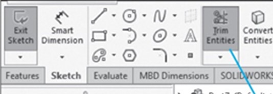
The TRIM ENTITIES tool (commonly just called the TRIM tool) is used to remove unwanted parts of an entity in the sketch. For example, you can trim a circle to create an arc segment. Or trim 2 crossing lines to create a right angle. The uses are infinite and powerful.
If you’ve used the trim tools in AutoCAD, you may have walked from that experience thinking that trimming is a pain. Luckily, trimming in Solidworks is fast and easy!
There are 5 options when using the TRIM tool. If you click on any of the 5 options, Solidworks will display a PropertyManager describing what it needs from you to perform the trim function. (See Figure 3-1 on Page 3-3 and below).
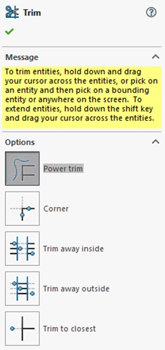
The option I use all the time is the “Power Trim” option. Read its description at the bottom of Page 3-3. Then try it for yourself. It is very easy to use. To trim away the unwanted portion of a sketch entity, press and hold the left mouse button band drag the cursor across the portion to remove. Note that a grey-colored “drag trace” line is displayed along the path of the cursor while the left mouse button is depressed.
Watch the following YouTube video to learn more about using the Power Trim option:
NOTE: When you are attempting to trim out some portions of your sketch, it is often advisable to zoom into the area you want to modify. Don’t work from 50,000 feet! Zoom in so you can see what you are doing.
You can look over the other 4 trim options. They really are for special situations. The truth is that you can use the Power Trim option to handle any trimming situation. That’s why I use it almost exclusively (and think you should to).
EXTENDING SKETCHED ENTITIES (page 3-6)
The EXTEND ENTITIES tool is used to extend existing lines in a sketch to new lengths. It can be used to length an existing rectangle as well.
You find this tool by clicking the down arrow on the TRIM ENTITIES command icon (see Figure 3-10 on Page 3-6 and below).
We just don’t use this capability very often. Just look over the other examples but don’t spend a lot of time. You can always reference back to this section at a later time if needed.
CONVERT ENTITIES (page 3-6)
We just don’t use this capability this semester. Just look over the other examples but don’t spend a lot of time. You can always reference back to this section at a later time if needed.
INTERSECTION CURVES (page 3-7)
We just don’t use this capability this semester. Just look over the other examples but don’t spend a lot of time. You can always reference back to this section at a later time if needed.
FILLETING SKETCHED ENTITIES (page 3-8) and CHAMFERING SKETCHED ENTITIES (page 3-9)
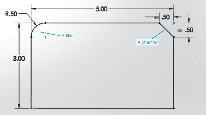
A “fillet” is a rounded corner or edge while a “chamfer” is a beveled (angled) corner or edge (see figure below):
Many parts out there in engineering have either a fillet, chamfer or both. There can be multiple occurrences of both on a single part. Creating these using the LINE tool (or chamfers) or the ARC tool (for rounds) would be tedious and error prone while sketching. Therefore, most CAD programs, including AutoCAD and Solidworks, have a specialized tool for creating these entities.
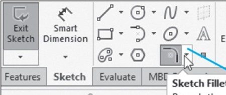
Solidworks has a combined FILLET and CHAMFER Command Icon which can be found on the Sketch CommandManager (see below). Use the “down arrow” on the right-hand side of the command icon to reveal the individual “Fillet” and “Chamfer” options.
Fillets are pretty straight forward. Follow the steps described in the text and look at Figures 3-18 and 3-19 on Page 3-9. It is noted here that the FILLET tool automatically trims the lines when it creates the fillet arc between the two lines, whether they originally intersected or not.
NOTE: Fillets are based on the RADIUS of the arc, not the diameter!
Chamfers are a little more complicated as there are 3 different ways to define a chamfer:
- Angle-Distance
- Distance-Distance (unequal distance)
- Equal Distance (a “45 degree” chamfer)
Figure 3-21 on Page 3-10 (and below) does a good job illustrating the 3 different chamfers and their unique parameters:
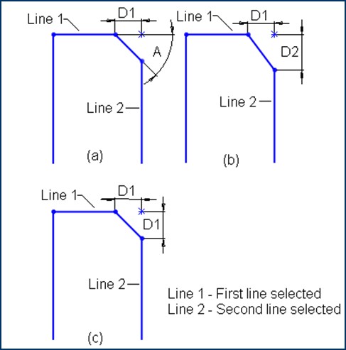
Most chamfers are “equal distance” (45 degree”) types as depicted by (c) in Figure 3-21.
OFFESTTING SKETCHED ENTITIES (page 3-11)
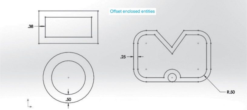
Most CAD programs have some sort of offset tool to automate the drawing of entities parallel to an existing entity at a specified offset distance. It can also create concentric circles (share the same center point). Although you can do this manually, it can be extremely tedious and error prone to have to recreate all the entities of a complex sketch at the offset distance. Some examples of the use of an offset tool is shown below:
Solidworks has an OFFSET ENTITIES Command icon which is found in the Sketch CommandManager. This can be a very useful tool and is often underutilized.
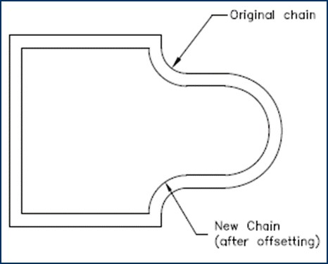
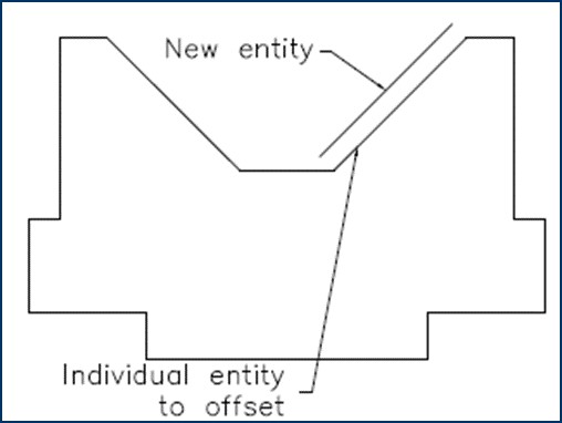
As shown in Figures 3-23 and 3-24 on Page 3-12 (and shown below), you can select an entire “chain” of entities to offset or just a single entity:
OFFESTTING EDGES OR FACE OF A MODEL (page 3-12)
We just don’t use this capability this semester. Just look over the other examples but don’t spend a lot of time. You can always reference back to this section at a later time if needed.
MIRRORING SKETCHED ENTITIES (page 3-14)
One of the adages in modeling is “we only sketch an entity once no matter how many times it is used in the model”. Obeying this adage is one of the ways we become efficient modelers.
Most CAD programs have some sort of mirror tool to automate the drawing of mirror images of an existing entity. Although you can do this manually, it can be extremely tedious and error prone to have to recreate all the entities of a complex sketch multiple times. The mirror image created is an exact copy of the original entity.
Solidworks has a MIRROR ENTITIES Command Icon located on the Sketch CommandManager. It is commonly just referred to as the MIRROR tool (see below).
Below is an example of a mirrored entity:
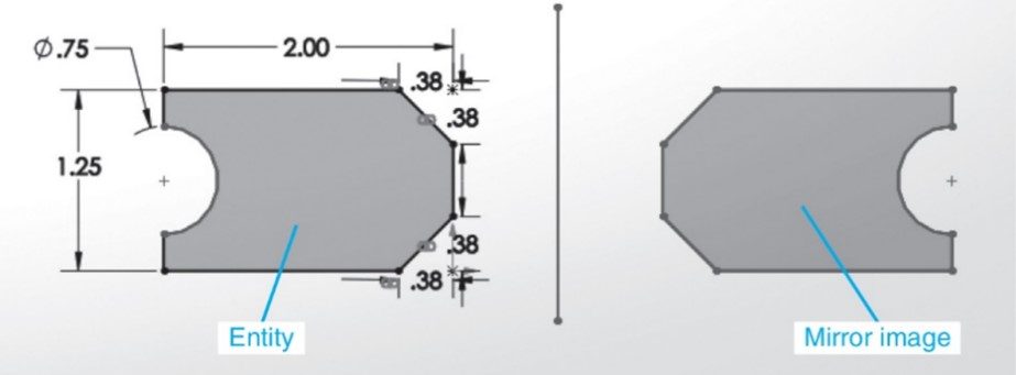
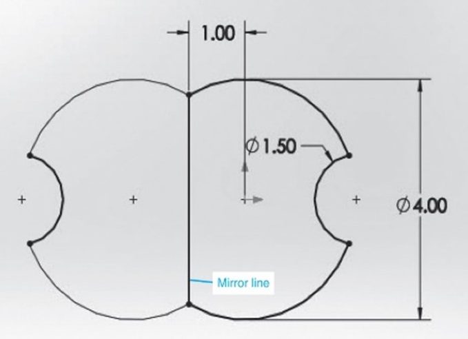
Note the vertical line running between the original entity on the left and the mirror image copy on the right. This line is called a “mirror line”. The mirror line is typically inserted into the sketch using a “centerline” line type in the LINE command. Note that the distance of the mirror line from the original entity most likely will be important. See an example below:
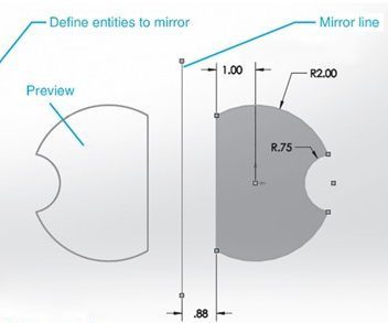
The edge of the original entity to be mirrored can also be selected as the mirror line. When that is done, the original and the mirror image would touch each other at the edge selected as the mirror line. See the example below. We don’t use this approach very often.
Mirror can be a very useful tool. You should practice it until you feel comfortable with using it. Getting it to work properly can be a bit tricky.
NOTE: Single copies of an entity which are not mirrored are created with the COPY ENTITY tool described later in this chapter starting on Page 3-21.
MIRRORING ENTITIES DYNAMICALLY (page 3-15)
Although this is a pretty cool tool, it really doesn’t provide any additional capability that we need for this course beyond the standard MIRROR ENTITIES command. If you do decide to try this tool out, you will need to access it through the TOOLS Solidworks menu (see grey box at the top of Page 3-15).
MOVING SKETCHED ENTITIES (page 3-16)
Most CAD programs have some sort of ability to move an entity from one location to another. This functionality does not make a copy of the entity – it just moves it. [See COPY ENTITIES starting on Page 3-21 for how we make a single copy of an entity.]
Solidworks has a MOVE ENTITIES Command Icon located on the Sketch CommandManager.
Like the FILLET and CHAMFER tools which share a command icon, it should be noted that if the down arrow on the right-hand side of the MOVE ENTITIES Command Icon would reveal the COPY ENTITIES tool. The ROTATE, SCALE and STRETCH tools are also accessed here.
This can be a very useful tool, although we don’t really use it too often.
NOTE: Although there are 2 different methods to move an entity (From/To and X/Y), we predominately use the From/To method. See the bottom of Page 3-17 for a description of this method. You should practice it until you feel comfortable with using it. Getting it to work properly can be a bit tricky.
ROTATING SKETCHED ENTITIES (page 3-17)
I don’t use this tool very often. Just read it over and reference later if needed. This tool is accessed using the down arrow on the MOVE ENTITIES Command Icon. Just look over the other examples but don’t spend a lot of time. You can always reference back to this section at a later time if needed.
SCALING SKETCHED ENTITIES (page 3-19)
I don’t use this tool very often. Just read it over and reference later if needed. This tool is accessed using the down arrow on the MOVE ENTITIES Command Icon. Just look it over but don’t spend a lot of time. You can always reference back to this section at a later time if needed.
STRETCHING SKETCHED ENTITIES (page 3-19)
I don’t use this tool very often. Just read it over and reference later if needed. This tool is accessed using the down arrow on the MOVE ENTITIES Command Icon. Just look it over but don’t spend a lot of time. You can always reference back to this section at a later time if needed.
COPYING AND PASTING SKETCHED ENTITIES (page 3-21)
The COPY ENTITIES tool in Solidworks is used to make a single copy of an original entity. The original entity remains intact at its original location when the copy is made. Note that there really isn’t a “paste” command – that function is part of the COPY command.
This tool works similarly to the MOVE ENTITIES tool.
This can be a very useful tool. You should practice it until you feel comfortable with using it. Getting it to work properly can be a bit tricky.
CREATING PATTERNS (page 3-21)
We shift gears away from editing sketched entities at this point and move into how to create sketch patterns.
Some parts we create need to have sketched entities placed in a particular arrangement such as along a linear edge or around a circle. A circular bolt pattern used on flanges is good example of this:
Being able to create a “pattern” of multiple copies of an entity is another way to help us obey the old adage “we only sketch an entity once no matter how many times it is used in the model”.
Most CAD programs have some sort of patterning tool to automate the drawing of multiple copies of an existing entity in a pattern – whether a linear (straight line) pattern or a circular pattern. Although you can do this manually, it can be extremely tedious and error prone to have to recreate all the entities of a complex sketch multiple times. The copies created are exact copies of the original entity.
CREATING LINEAR SKETCH PATTERNS (page 3-22)
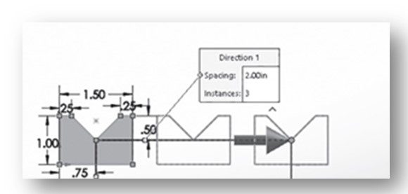
Below is an example of a pattern created with the LINEAR SKETCH PATTERN tool. It created two copies of the original entity along the X-axis. They are spaced 2 inches apart.
Two-dimensional patterns can also be created. Below is a 3 x 5 pattern:
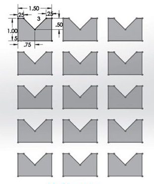
Solidworks has a LINEAR SKETCH PATTERN Command Icon located on the Sketch CommandManager. It is used to create a pattern of exact copies of the original entity in the X- and or Y-directions at specified spacings (spacings in the directions do not have to be the same).
Like the FILLET and CHAMFER tools which share a command icon, it should be noted that if the down arrow on the right-hand side of the LINEAR SKETCH PATTERN Command icon would reveal the CIRCULAR SKETCH PATTERN tool.
Carefully read over the discussion of how to create a linear sketch pattern running from Page 3-22 through 3-24. Getting it to work properly can be a bit tricky. This can be a very useful tool. You should practice it until you feel comfortable with using it.
Watch the video below to learn more about how to create a linear sketch pattern:
CREATING CIRCULAR SKETCH PATTERNS (page 3-25)
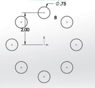
The CIRCULAR SKETCH PATTERN tool in Solidworks is used to create patterns of an original entity in a full circle or in an arc.
This tool is used frequently in practice as many mechanical parts have bolts laid out in a circular pattern. This arrangement is common on pipe flanges. Below is a typical circular pattern showing eight 0.75-inch diameter holes equally spaced along a circle of radius 2 inches. This 4-inch diameter circle is called the “bolt circle” in engineering practice. In this example the center point of the pattern is located at the origin.
This tool works similarly to the LINEAR SKECTCH PATTERN tool.
Carefully read over the discussion of how to create a circular sketch pattern running from Page 3-25 through 3-27. Getting it to work properly can be a bit tricky. This can be a very useful tool. You should practice it until you feel comfortable with using it.
Watch the video below to learn more about creating circular sketch patterns:
EDITING PATTERNS (page 3-27)
Yes, sketch patterns (linear or circular) can be edited after you create them. You can activate a short-cut menu (see Figure 3-56 on Page 3-27 and below) by right-clicking on the instance of the pattern you wish to edit:
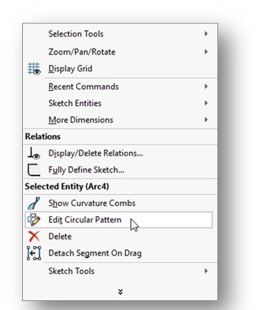
Then select from the menu either Edit Circular Pattern or Edit Linear Pattern, depending upon which type of pattern you are editing.
Remember one thing – if you create a pattern of holes of a given diameter, ALL the holes in the pattern will always stay the same. You cannot edit the diameter of just one of the holes. With respect to entities in patterns, I remember this by the phrase: “birds of a feather fly together”.
WRITING TEXT IN THE SKETCHING ENVIRONMENT (page 3-28)
You can also write text in the sketching environment and use it to later emboss or engrave into a 3D feature. We just don’t use this capability this semester. Just look it over but don’t spend a lot of time. You can always reference back to this section at a later time if needed.
MODIFYING SKETCHED ENTITIES (page 3-29)
As we said earlier, most sketches require modification at some point in the design process. How to modify various sketch entities is discussed in this final section of this chapter. I’m only going to talk to the ones we might use this semester.
Quite honestly, once we get into Chapter 4 and discuss applying dimensions using the Smart Dimension tool and geometric relations to sketch entities, we really don’t use these modification tools much.
MODIFYING A SKETCH LINE (page 3-29)
You can modify the attributes of a sketched line by using the Line Properties PropertyManager which is displayed when you select a line by left-clicking on it in the sketch. You can modify the values in the respective edit boxes that are displayed.
Note the information given in the text about what happens when you attempt to modify a line that is part of a rectangle or polygon. It is noted that you do not have to “explode” these types of entities in Solidworks like you do in AutoCAD – individual line segments can be modified. Of course, the rectangle or polygon is going to change based on that modification.
MODIFYING A SKETCHED CIRCLE (page 3-30)
Just like we just discussed for a line, you can modify the attributes of a sketched circle by using the Arc Properties PropertyManager which is displayed when you select a circle by left-clicking on it in the sketch. Remember that a circle is really an arc! You can modify the values in the respective edit boxes that are displayed.
MODIFYING A SKETCHED ARC (page 3-29)
Works similarly as described in Modifying a Sketched Circle above.
MODIFYING A SKETCHED POLYGON (page 3-29)
Again, nothing different here except we’re talking about modifying a polygon. Not used tyoo often.
MODIFYING A SPLINE (page 3-30)
We just don’t use this capability this semester. Just look it over but don’t spend a lot of time. You can always reference back to this section at a later time if needed. This includes topics from Page 3-30 through 3-32 for splines.
MODIFYING THE COORDINATES OF A POINT (page 3-32)
We just don’t use this capability this semester. Just look it over but don’t spend a lot of time. You can always reference back to this section at a later time if needed.
MODIFYING AN ELLIPSE OR AN ELLIPTICAL ELLIPSE (page 3-32)
We just don’t use this capability this semester. Just look it over but don’t spend a lot of time. You can always reference back to this section at a later time if needed.
MODIFYING A PARABOLA (page 3-32)
We just don’t use this capability this semester. Just look it over but don’t spend a lot of time. You can always reference back to this section at a later time if needed.
DETACHING MODIFYING AND COPYING SKETCHED ENTITIES (page 3-32)
We just don’t use this capability this semester. Just look it over but don’t spend a lot of time. You can always reference back to this section at a later time if needed.
SPLITTING SKETCHED ENTITIES (page 3-33)
We just don’t use this capability this semester. Just look it over but don’t spend a lot of time. You can always reference back to this section at a later time if needed.
CREATING SEGMENTS IN SKETCHED ENTITIES (page 3-33)
We just don’t use this capability this semester. Just look it over but don’t spend a lot of time. You can always reference back to this section at a later time if needed.
Congratulations! You are done With Chapter 3!
