Magnetism
Last Update: 7/5/2022
magnets
All magnets attract iron, such as that in a refrigerator door. However, magnets may attract or repel other magnets. Experimentation shows that all magnets have two poles. If freely suspended, one pole will point toward the north. The two poles are thus named the north magnetic pole and the south magnetic pole (or more properly, north-seeking and south-seeking poles, for the attractions in those directions).
It is a universal characteristic of all magnets that like poles repel and unlike poles attract, as demonstrated in Figure 26.1. (Note the similarity with electrostatics: unlike charges attract and like charges repel.)

Further experimentation shows that it is impossible to separate the north and south poles in the manner that + and − charges can be separated. As illustrated in Figure 26, the north and south poles always occur in pairs. Attempts to separate them result in more pairs of poles. If we continue to split the magnet, we will eventually get down to an iron atom with a north pole and a south pole—these, too, cannot be separated.

The Earth acts like a very large bar magnet with its south-seeking pole near the geographic North Pole. That is why the north pole of your compass is attracted toward the geographic north pole of the Earth—because the magnetic pole that is near the geographic North Pole is actually a south magnetic pole! Confusion arises because the geographic term “North Pole” has come to be used (incorrectly) for the magnetic pole that is near the North Pole. Thus, the “North magnetic pole” is actually a misnomer—it should be called the South magnetic pole.

Only certain materials, such as iron, cobalt, nickel, and gadolinium, exhibit strong magnetic effects. Such materials are called ferromagnetic. A group of materials made from the alloys of the rare earth elements is also used as strong and permanent magnets; a popular one is neodymium. Other materials exhibit weak magnetic effects, which are detectable only with sensitive instruments. Not only do ferromagnetic materials respond strongly to magnets (the way iron is attracted to magnets), they can also be magnetized themselves—that is, they can be induced to be magnetic or made into permanent magnets.
When a magnet is brought near a previously unmagnetized ferromagnetic material, it causes local magnetization of the material with unlike poles closest. What happens on a microscopic scale is illustrated in Figure 26.4. The regions within the material called domains act like small bar magnets. Within domains, the poles of individual atoms are aligned. Each atom acts like a tiny bar magnet. Domains are small and randomly oriented in an unmagnetized ferromagnetic object. In response to an external magnetic field, the domains may grow to millimeter size, aligning themselves as shown in Figure 26.4(b). This induced magnetization can be made permanent if the material is heated and then cooled, or simply tapped in the presence of other magnets.

Conversely, a permanent magnet can be demagnetized by hard blows or by heating it in the absence of another magnet. Increased thermal motion at higher temperature can disrupt and randomize the orientation and the size of the domains.
The source of all magnetism is an electric current. Ferromagnetism, for example, results from an internal cooperative alignment of electron spins, possible in some materials but not in others.
Since two magnets apply forces on each other without any contact, it is helpful to use the concept of field to explain this interaction. A magnet generates a magnetic field around it. When another magnet is brought near, the magnetic fields of the two magnets interact. The result of this interaction is the force that each magnet experiences. Mathematically, the magnetic field is a vector quantity with magnitude and direction. The figures below illustrate magnetic field lines around a coil that carries an electric current, around bar magnets, and in the region between two unlike poles and two like poles of two separate magnets.


Extensive exploration of magnetic fields has revealed a number of hard-and-fast rules. We use magnetic field lines to represent the field (the lines are a pictorial tool, not a physical entity in and of themselves). The properties of magnetic field lines can be summarized by these rules:
- The direction of the magnetic field is tangent to the field line at any point in space. A small compass will point in the direction of the field line.
- The strength of the field is proportional to the closeness of the lines.
- Magnetic field lines can never cross, meaning that the field is unique at any point in space.
- Magnetic field lines are continuous, forming closed loops without beginning or end. They go from the north pole to the south pole.
The last property is related to the fact that the north and south poles cannot be separated.
The magnetic field is represented with  , and measured in units of Tesla (T).
magnetic force on a moving charge
What is the mechanism by which one magnet exerts a force on another? The answer is related to the fact that all magnetism is caused by current, the flow of charge. Magnetic fields exert forces on moving charges, and so they exert forces on other magnets, all of which have moving charges.
The magnitude of the magnetic force on a moving charge is given by
 Magnetic Force On A Moving Charge
In this equation
 is the magnitude of the electric charge, in C
 is the magnitude of the velocity of the charge, in m/s
 is the magnitude of the external magnetic field in which the charge is moving, in T
 is the angle between
  and
and
This force is often called the Lorentz force.
The direction of the magnetic force on a moving charge is determined by using the Right-Hand-Rule, illustrated in Figure 26.6, and explained below.

Right-Hand-Rule:
Place your right hand in the direction of . Next, close your hand in the direction of . Your thumb points in the direct on of the force on a positive charge. The direction of the force on a negative charge is opposite to the direction of the force on the positive charge.
Example 26.1
An alpha-particle, q= 3.2×10⁻¹⁹C moves through a uniform magnetic field whose magnitude is 1.5 T. The field is directly parallel to the positive z-axis. What is the magnetic force on the alpha-particle when it is moving
(a) in the positive x-direction with a speed of 5.0×10⁴m/s?
(b) in the negative y-direction with a speed of 5.0×10⁴m/s?
(c) in the positive z-direction with a speed of5.0x104m/s?
Solution for (a)
Using Right-Hand-Rule we see that the force is along the -y axis, as shown in Figure 26.7(a)

The magnitude of the force is given by


Therefore the magnetic force on the alpha particle is 
Solution for (b)
Using Right-Hand-Rule we see that the force is along the -x axis, as shown in Figure 26.7(b)

The magnitude of the force is the same as we found in (a), because the magnitude of charge, velocity, magnetic field, and the angle between the velocity and magnetic field are the same as (a).
Therefore the magnetic force on the alpha particle is 
Solution for (c)
Since the velocity vector and the magnetic field are both along the z-axis, the angle between them is zero.

Therefore the magnetic force on the alpha particle is 
Magnetic force is always perpendicular to velocity so that it does no work on the charged particle. The particle’s kinetic energy and speed thus remain constant. The direction of motion is affected, but not the speed. This is typical of uniform circular motion. The simplest case occurs when a charged particle, such as an electron, moves perpendicular to a uniform field, such as shown in Figure 26.8.

The particle has a centripetal acceleration ( ) due to the continuous change in the direction of the velocity vector. Applying Newton’s Second Law to this motion yields

Since  , the equation above can be simplified and rearranged as

If the velocity is not perpendicular to the magnetic field, then v is the component of the velocity perpendicular to the field. The component of the velocity parallel to the field is unaffected since the magnetic force is zero for motion parallel to the field. This produces a spiral motion rather than a circular one, as shown in Figure 26.9.

magnetic force on a current-carrying wire
We can derive an expression for the magnetic force on a current by taking a sum of the magnetic forces on individual charges. The force on an individual charge moving at the drift velocity  is given by
  . Taking to be uniform over a length of wire and zero elsewhere, the total magnetic force on the wire is then
  , where N is the number of charge carriers in the section of wire of length l. Now, N=nV, where n is the number of charge carriers per unit volume and V is the volume of wire in the field. Noting that V=Al, where A is the cross-sectional area of the wire, then the force on the wire is
  . Gathering terms we get
  . Since
  (see UNIT 24)
 Force On A Current Carrying Wire
 is the current in the wire
 is the length of the wire in the magnetic field
 is the magnetic field is the angle between the wire and the magnetic field
Example 26.2
A wire of length 50 cm and mass 10 g is suspended in a horizontal plane by a pair of flexible leads (Figure 26.10). The wire is then subjected to a constant magnetic field of magnitude 0.50 T, which is directed as shown. What are the magnitude and direction of the current in the wire needed to remove the tension in the supporting leads?

Solution
From the free-body diagram below we see that the tensions in the supporting leads go to zero when the gravitational and magnetic forces balance each other. Using the Right-Hand-Rule, we find that the magnetic force points up when the current is to the right. We can then determine the size of the current by equating the gravitational force and the magnetic force.


Since the angle between the wire and the magnetic field is 90º, we get


force and torque on a current loop
Motors are the most common application of magnetic force on current-carrying wires. Motors have loops of wire in a magnetic field. When current is passed through the loops, the magnetic field exerts a torque on the loops, which rotates a shaft. Electrical energy is converted to mechanical work in the process. This is shown in Figure 26.12.

Let us examine the force on each segment of the loop in Figure 26.12 to find the torques produced about the axis of the vertical shaft. We take the magnetic field to be uniform over the rectangular loop, which has width w and height l. First, we note that the forces on the top and bottom segments are vertical and, therefore, parallel to the shaft, producing no torque. Those vertical forces are equal in magnitude and opposite in direction so that they also produce no net force on the loop. Figure 26.13 shows views of the loop from above. Torque is defined as  where F is the force, r is the distance from the pivot that the force is applied, and Θ is the angle between r and F. As seen in Figure 26.13(a), right-hand rule gives the forces on the sides to be equal in magnitude and opposite in direction so that the net force is again zero. However, each force produces a clockwise torque. Since r=w/2 the torque on each vertical segment is (w/2)FsinΘ and the two add to give a total torque.


Now, each vertical segment has a length l that is perpendicular to B, so that the force on each is  . Entering F into the expression for torque yields

If we have a coil with multiple loops of N turns, we get N times the torque of one loop. Finally, note that the area of the loop is A=wl, the expression for the torque becomes
 Torque On A Coil
In this equation
 is the number of turns in the coil
is the current in the coil
 is the area of the coil
is the magnetic field the coil is in
is the angle between a line perpendicular to the area of the coil and the magnetic field.
Example 26.3
Find the maximum torque on a 100-turn square coil of a wire of 10.0 cm on a side that carries 15.0 A of current in a 2.00-T field.
Solution
Torque on a coil is maximum when Θ=90°.


Here is an excellent description of how a DC motor works.
Attribution
This chapter contains material taken from Openstax College Physics -Magnetism, and Openstax University Physics Volume 2-Magnetic Forces and Fields and is used under a CC BY 4.0 license. Download these books for free at Openstax
To see what was changed, refer to the List of Changes.
problems
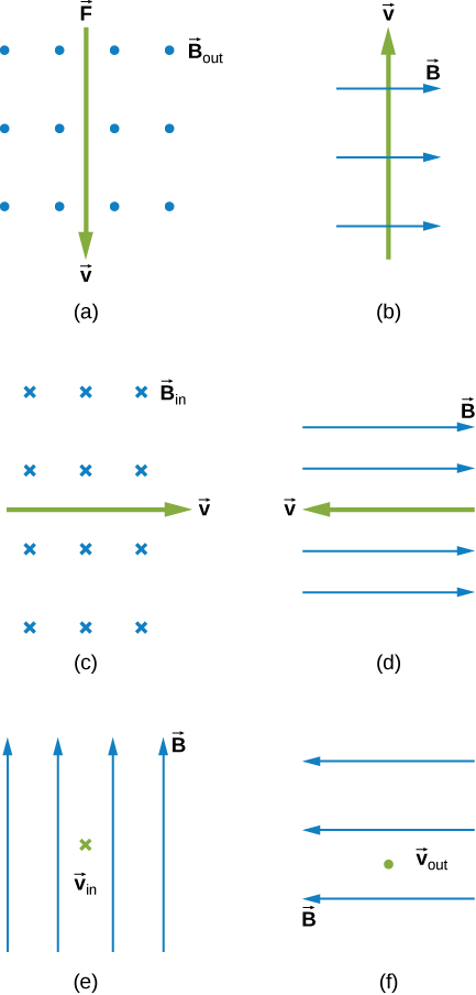
- [openstax univ. phys. vol.2 – 11.15 and 11.16]Find the direction of the magnetic force on a point charge moving with velocity in the magnetic field
- If the charge is positive.
- If the charge is negative.
- [openstax univ. phys. vol. 2 – 11.17 and 11.18] . Find the direction of the velocity of a point charge that experiences the magnetic force shown in each of the three cases, assuming it moves perpendicular to B
- if the charge is negative.
- if the charge is positive.

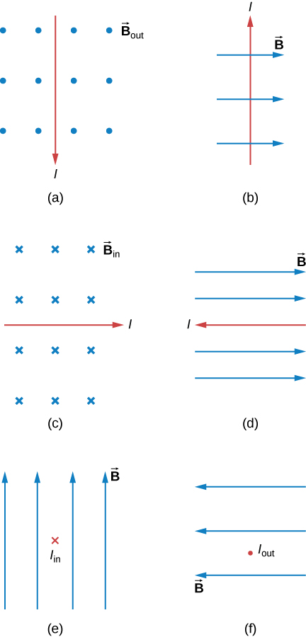
- [openstax univ. phys. vol. 2 – 11.19 and 11.20] Determine the direction of the magnetic field that produces the magnetic force on a point charge as shown in each of the three cases, assuming is perpendicular to
- if the charge is positive.
- if the charge is negative.

- [openstax univ. phys. vol. 2 – 11.23] An electron moving at 4.00×10³ m/s in a 1.25-T magnetic field experiences a magnetic force of 1.40×10⁻¹⁶N. What angle does the velocity of the electron make with the magnetic field? There are two answers.
- [openstax univ. phys. vol. 2 – 11.22] A cosmic ray proton moving toward Earth at 5.00×10⁷m/s experiences a magnetic force of 1.70×10⁻¹⁶N.
- What is the strength of the magnetic field if there is a 45º angle between it and the proton’s velocity?
- Is the value obtained in part (a) consistent with the known strength of Earth’s magnetic field on its surface?
- [openstax univ. phys. vol.2 – 11.28] An electron in a TV CRT moves with a speed of 6.00×10⁶m/s in a direction perpendicular to Earth’s field, which has a strength of 5.00×10⁻⁵.
- What strength electric field must be applied perpendicular to the Earth’s field to make the electron move in a straight line?
- If this is done between plates separated by 1.00 cm, what is the voltage applied? (Note that TVs are usually surrounded by a ferromagnetic material to shield against external magnetic fields and avoid the need for such a correction.)
- [openstax univ. phys. vol. 2 – 2.28(edited)] What is the direction of the magnetic force on the current in each of the six cases?
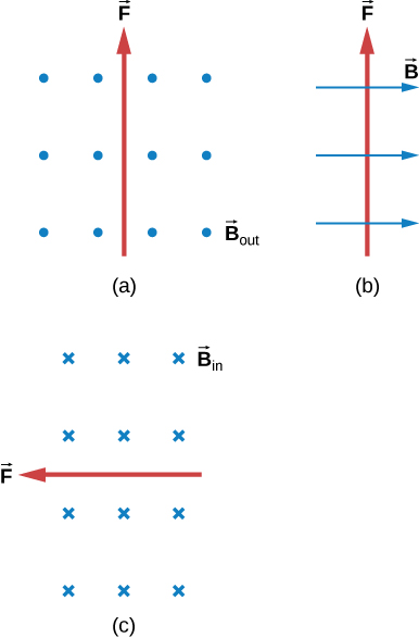
- [openstax univ. phys. vol. 2 – 11.34] What is the direction of a current that experiences the magnetic force shown in each of the three cases, assuming the current runs perpendicular to ?
- [openstax univ. phys. vol. 2 – 11.37] A dc power line for a light-rail system carries 1000 A at an angle of 30.0º to Earth’s 5.00×10⁻⁵T field. What is the force on a 100-m section of this line?
- [openstax univ. phys. vol. 2 – 11.38] A wire carrying a 30.0-A current passes between the poles of a strong magnet that is perpendicular to its field and experiences a 2.16-N force on the 4.00 cm of wire in the field. What is the average strength of the magnetic field?
- [openstax univ. phys. vol. 2 – 11.40] A 150-turn square loop of wire 18.0 cm on a side that carries a 50.0-A current is placed in a magnetic field of magnitude 1.60T.
- What is the maximum torque on this current loop?
- What is the torque when θ is 10.9º?
- [openstax univ. phys. vol. 2 – 11.41] A wire loop has 50 square turns that are 15.0 cm on a side and is in a uniform 0.800T magnetic field. Find the current needed through this loop to create a maximum torque of 9.00Nm.


