Dynamics – Forces and Motion
Last Update: 12/01/2022
friction
Friction is a force that opposes relative motion between surfaces in contact. Imagine, for example, trying to slide a heavy crate across a concrete floor—you may push harder and harder on the crate and not move it at all. While you are pushing and the crate is not moving, the friction force between the crate and the floor is called static friction. But if you finally push hard enough, the crate eventually slips suddenly and starts to move. Once in motion it is easier to keep the crate in motion than it was to get it started. The type of friction between the crate and the floor while the crate is sliding is called kinetic friction.
Experimentally, we know that the magnitude of the kinetic friction force and the magnitude of the force needed to get the object moving are directly proportional to the force that pushes the two surfaces together. The term we use for the force that pushes the two surfaces together is the normal force. If you add mass to the crate, say by placing a box on top of it, the force between the crate and the floor becomes larger and you need to push even harder to get it started and also to keep it moving. This is because the additional mass of the box on the crate increases the size of the normal force that the concrete floor applies to the crate. Kinetic friction also depends on the properties of the two surfaces. If you oiled the concrete you would find it to be easier to get the crate started and keep it going. These observations lead to the following equation for kinetic friction:
 Kinetic Friction Force
In this equation,  is the magnitude of kinetic friction,
  , is the coefficient of kinetic friction, a dimensionless constant that depends on the properties of the two surfaces, and
  is the magnitude of the normal force. The direction of kinetic friction is always opposite to the direction of motion.
A rather surprising fact about friction is that the magnitude of this force is independent of the area of contact between the two surfaces. Consider two blocks of the same mass, but different surface areas as shown in Figure 9.1. The force necessary to move the blocks at a constant speed is the same even though the block in (a) has twice the contact area as the block in (b).

The other type of friction, static friction, occurs when two surfaces are stationary relative to each other. In the previous example, when the crate is resting on the floor and nobody is pushing it, the static friction between the crate and the floor is zero. As you start pushing and gradually increase your pushing force, the static friction force increases as well until you push hard enough that the crate slips and starts to slide along the floor. Thus the magnitude of static friction can vary from zero to some maximum value, (fs)max, when the pushed object begins to slip.
 Range Of Static Friction Force
Through experimentation, we know that the magnitude of the maximum static friction force,  , is proportional to the magnitude of the normal force.
 Maximum Static Friction Force
The coefficient of static friction, μs, is dependent on the properties of the two surfaces. This dimensionless constant is almost always slightly greater than the constant μk associated with kinetic friction,

This small difference accounts for the fact that a greater force is needed to overcome static friction and make an object start sliding than the force needed to overcome kinetic friction and maintain sliding at constant velocity. To understand why that’s the case, consider Figure 9.2 which is a crude pictorial representation of how friction occurs at the interface between two objects. Close-up inspection of these surfaces shows them to be rough. So when you push to get an object moving (in this case, a crate), you must raise the object until it can skip along with just the tips of the surface hitting, break off the points, or do both. A considerable force can be resisted by friction with no apparent motion. The harder the surfaces are pushed together (such as if another box is placed on the crate), the more force is needed to move them. Part of the friction is due to adhesive forces between the surface molecules of the two objects, which explain the dependence of friction on the nature of the substances. Adhesion varies with substances in contact and is a complicated aspect of surface physics. Once an object is moving, there are fewer points of contact (fewer molecules adhering), so less force is required to keep the object moving. A small but nonzero speeds, friction is nearly independent of speed.

SYNOVIAL JOINT FRICTION
Static and kinetic friction are both present in joints. Static friction must be overcome, by either muscle tension or gravity, in order to move. Once moving, kinetic friction acts to oppose the motion, causes wear on joint surfaces, generates thermal energy, and makes the body less efficient. The body uses various methods to decrease friction in joints, including synovial fluid, which serves as a lubricant to decrease the coefficient of friction between bone surfaces in synovial joints (the majority of joints in the body). Bone surfaces in synovial joints are also covered with a layer of articular cartilage which acts with the synovial fluid to reduce friction and provides something other than the bone surface to wear away over time We will ignore friction when analyzing our forearm as a lever because the frictional forces are relatively small and because they act inside the joint, very close to the pivot point so they cause negligible torque.

Synovial joints allow for smooth movements between the adjacent bones. The joint is surrounded by an articular capsule that defines a joint cavity filled with synovial fluid. The articulating surfaces of the bones are covered by a thin layer of articular cartilage. Ligaments support the joint by holding the bones together and resisting excess or abnormal joint motions.
Example 9.1
A 20.0-kg crate is at rest on a floor as shown in Figure 9.3. The coefficient of static friction between the crate and floor is 0.700 and the coefficient of kinetic friction is 0.600. A horizontal force  is applied to the crate. Find the force of friction, and the acceleration of the crate if (a)
  , (b)
, (b)  , (c)
, (c) , and (d)
 . In all cases is parallel to the floor.
 |

|
Solution for (a)
Step 1 – The free-body diagram for the crate is shown in Figure 9.3(b)
Step 2 – If the crate accelerates, the acceleration is parallel to the floor. Therefore we can take the x-axis to be horizontal with the positive direction to the right, parallel to the acceleration, and the y-axis vertical, with the positive direction upward.
Step 3 – Since all the forces are along the x and y axes, there is no component to draw or calculate.
Step 4 and Step 5– In order to see what type of friction, static or kinetic, exists between the floor and the crate we must compare the size of the applied force, P, to the size of the maximum value of static friction and the kinetic friction force. Since fk = μkN, and (fs)max= μsN, we need to determine the normal force, N, first.
Applying Newton’s Second Law in the y-direction yields


Now we can calculate fk, and (fs)max.
|
|

|


Since 20.0N, is less than the force necessary to overcome static friction,(fs)max, the crate doesn’t slide (ax=0), and the static friction force between the crate and the floor is also 20.0N.
Solution for (b)
Same reasoning as (a). Now fs = 30.0N
Solution for (c)
Same reasoning as (a). Now fs = 120.0N
Solution for (d)
Now the applied force, P is greater than the maximum static friction force. Therefore the crate slides on the floor and the type of friction between the crate and the floor is kinetic friction. Therefore, in this case, fk = 118 N. Let’s apply Newton’s Second Law in the x-direction to find the acceleration.


Discussion
This example illustrates how we consider friction in a dynamics problem. Notice that static friction has a value that matches the applied force until we reach the maximum value of static friction. Also, no motion can occur until the applied force equals the maximum value of static friction. Finally, when the motion does occur, the force of kinetic friction is less than the maximum value of static friction and will remain constant throughout the motion.
Video Example – Book sliding up a ramp with friction
Example 9.2
A skier with a mass of 62 kg is sliding down a snowy slope at a constant acceleration. Find the coefficient of kinetic friction for the skier if friction is known to be 45.0 N.

Solution
Step 1 – The free-body diagram for the skier includes the gravitational force (weight), W, the normal force, N, and the friction force, f, as shown in Figure 8.2.
Step 2 –The acceleration is parallel to the slope. Therefore we can take the x-axis to be along the slope with the positive direction down the slope, and the y-axis perpendicular to the slope with the positive direction up in the direction of the normal force.
Step 3 – The gravitational force, W, has components along the x and y axes, as shown on the free-body diagram. Let’s calculate these components.
|
|
|


Step 4 and Step 5– Applying Newton’s Second Law in the y-direction yields


Now we can solve for the coefficient of kinetic friction.


Example 9.3
A 50.0-kg crate rests on the bed of a truck as shown in Figure 9.4. The coefficients of friction between the surfaces are μk=0.300 and μs=0.400. Find the frictional force on the crate when the truck is accelerating forward relative to the ground at (a) 2.00 m/s2, and (b) 5.00 m/s2.
 |
 |
Solution for (a)
Step 1 – The free-body diagram for the crate includes the gravitational force (weight), W=490N, the normal force, N, and the friction force, f, as shown in Figure 9.4.
 |
 |
 |
Step 2 –The acceleration is horizontal. Therefore we can take the x-axis to be horizontal with the positive direction to the right, and the y-axis to be vertical with the positive direction upward.
Step 3 – Since all the forces on the crate are along the x and y axes, there is no component to draw or to calculate.
Step 4 and Step 5 –Let’s first determine the magnitude of the maximum static friction force and the kinetic friction force. To do this, we need to find the normal force, N.
Applying Newton’s Second Law in the y-direction yields


Now let’s find the friction forces.
|
|
|


If the crate is not sliding on the bed of the truck, then it’s acceleration relative to the ground must be the same as the acceleration of the truck. Let’s see what friction force is needed to cause this acceleration.


Since this force is less than the maximum static friction force, (fs)max, then the friction between the crate and the bed of the truck is static friction, and fs = 100N.
Solution for (b)
The reasoning is similar to (a). We need to find out what friction force causes an acceleration equal to that of the truck.


Since this is greater than the maximum value for the static friction force,(fs)max, it means that the crate is sliding on the bed of the truck. Therefore the friction between the crate and the bed of the truck is kinetic friction and fk=147N. Now, let’s determine the acceleration of the crate relative to the ground.


Discussion:
Relative to the ground, the truck is accelerating forward at 5.0m/s2 and the crate is accelerating forward at 2.94m/s2. Hence the crate is sliding backward relative to the bed of the truck with an acceleration of 2.94m/s2−5.00m/s2=−2.06m/s2.
Video Example – Pushing a block against a wall
Example 9.4
The snowboarder in Figure 9.5 glides down a slope. The coefficient of kinetic friction between the board and the snow is μk=0.20.
a) What is the acceleration of the snowboarder if the slope is inclined at θ=13° to the horizontal?
b) What is the acceleration of the snowboarder, if the slope is inclined at θ=10° to the horizontal?
 |
 |
Step 1 – The free-body diagram for the snowboarder includes the gravitational force (weight), W, the normal force, N, and the friction force, f, as shown in Figure 9.5.
Step 2 –The acceleration is parallel to the incline. Therefore we can take the x-axis to be parallel to the incline with the positive direction down the incline, and the y-axis to be perpendicular to the incline with the positive direction up in the direction of the normal force.
Step 3 – The components of the gravitational force are shown on the free-body diagram. Let’s calculate these components. Notice that angle a=13°, and that W=mg
|
|
|


Step 4 and Step 5 – Applying Newton’s Second Law in the x-direction and y-direction yields
 |
 |
|
|
|


Since the friction is kinetic friction

Therefore

![a_x=(9.8m/s^2)[Sin 13^\circ-(0.20)(Cos13^\circ)]](https://pressbooks.pub/app/uploads/quicklatex/quicklatex.com-6cfa99bc98b2b753775ccb4ee858bcac_l3.png "Rendered by QuickLaTeX.com")

Solution for (b)
The reasoning is the same as for (a), but replacing 13° with 10° yields

![a_x=(9.8m/s^2)[Sin 10^\circ-(0.20)(Cos10^\circ)]](https://pressbooks.pub/app/uploads/quicklatex/quicklatex.com-afcee73ed1542677a4951f8b52d726ae_l3.png "Rendered by QuickLaTeX.com")

Discussion
Notice from this equation that if θ is small enough or μk is large enough, the ax is in opposite direction to the velocity, that is, the snowboarder slows down.
circular motion
Uniform Circular Motion (Constant speed)
As we saw in UNIT 6, when an object moves around a circular path with a constant speed, it has an acceleration, called the centripetal acceleration, that points toward the center of the circular path and is due to the change in the direction of the velocity vector. We also saw that the magnitude of this acceleration is given by

According to Newton’s Laws, the cause of any acceleration is an unbalanced force. Therefore all the forces that act on an object that moves around a circular path with constant velocity must add up to produce a net force that points toward the center of the circular path. The following simulation demonstrates this idea.
An example of circular motion is the space station orbiting the Earth. Why do astronauts inside the space station feel weightless? To answer this question, we first need to realize that what we feel as our weight is the normal force on our body from the surface we are resting on (the floor, the chair, etc.). For example, if we are in an elevator that is accelerating upward, we feel “heavier” than usual because the normal force on our body is greater than our weight. Similarly, if the elevator is accelerating downward, we feel “lighter”. If we were in free fall, there would be no normal force pushing up against our bodies, and we would feel weightless. The reason astronauts feel weightless is that they are continuously in free fall. At any instant, the velocity of the space station (and everything in it) is tangent to the circular orbit. At the same time, there is a gravitational force pulling the space station toward the center of the Earth. This causes the space station to change direction and fall toward the Earth. This happens continuously, which means that the space station is continuously in free-fall causing the occupants to feel weightless. The following diagram illustrates what happens when an object is projected horizontally with a greater and greater speed from a certain altitude above the surface of the Earth. At lower speeds, the result is projectile motion. The object moves farther and farther horizontally (parallel to the surface of the Earth) as it falls. Eventually, a speed is reached where the object ends up orbiting the Earth as it falls. For example, the orbital speed of the International Space Sation is 7.66km/s (4.76mi/s) at an orbit of 409km (254mi) above the surface of the Earth.

Example 9.5
A 900kg car goes around an unbanked curve with a radius of 500m at 25.0m/s. Find the minimum coefficient of static friction needed between the tires and the road that would prevent the car from slipping.
 |
 |
Figure 9.6(a) is the top view of a car going around a curve at a constant speed. At any given moment the acceleration of the car is a vector toward the center of the circular path (centripetal acceleration). When the car is on the right side of the center, the net force on the car must be directly to the left (toward the center) in order to produce a centripetal acceleration toward the center. Figure 9.7 shows the free body diagram for this car when it is to the right of the center.
Now we just follow the steps for applying Newton’s Second Law to this problem.
Step 1 – The free-body diagram for the car includes the gravitational force (weight), W, the normal force, N, and the static friction force, f. This free-body diagram is shown in Figure 9.7.
Step 2 –The acceleration is toward the center of the circular path, which is horizontal. Therefore, we pick the x-axis to be horizontal and positive to the left, and the y-axis to be vertical and positive upward.
Step 3 – Since all the forces are along the x and y axes, there are no components to draw or calculate.
Step 4 and Step 5 – Applying Newton’s Second Law in the x-direction and y-direction yields
|
|
|
|
|


This means that the static friction force must be at least equal to 1125N for the car to make the curve. From this, we can calculate the minimum coefficient of static friction.


Example 9.6
A ball of mass 0.300kg is attached to a string of length 0.400m and revolves uniformly in a horizontal circle with a radius of 0.150m as shown in Figure 9.8(a). Determine the tension in the string and the speed of the ball.

Solution
Step 1 – The free-body diagram for the ball includes the gravitational force (weight), W, and the tension force, T, as shown in Figure 9.8(b)

Step 2 –The acceleration is toward the center of the circular path, which is horizontal. Therefore, we pick the x-axis to be horizontal and positive to the left, and the y-axis to be vertical and positive upward.
Step 3 – The tension force, T, has x and y components. Let’s determine these components.
With the length of the string and the radius of the circle, we can determine the angle Θ.


Now we can find the components of T.
|
|
|


Step 4 and Step 5 – Since the ball is moving around a circle with constant speed, it has centripetal acceleration which depends on the speed.
Applying Newton’s Second Law in x and y directions will allow us to find this speed.
|
|
|
|
|


combining the two results we get:


So far we have only discussed circular motion with constant speed. Now we move on to circular motion with varying speeds. That’s when an object goes around a circle while speeding up or slowing down.
Non-uniform circular motion (speeding up / slowing down)
An object that goes around a circular path with varying speeds has an acceleration vector that no longer points toward the center of the circular path. In order to determine the size and direction of this acceleration, we need to understand what causes it first.
As we saw in UNIT 6, any circular motion involves a change in direction of velocity which produces a centripetal acceleration. In other words, the centripetal acceleration represents the rate of change in the direction of the velocity vector. If, in addition to the change in direction, the velocity vector also changes in size (speeding up or slowing down), then there is another acceleration that represents the rate of change of the magnitude of velocity. If the object is speeding up, this acceleration would be in the same direction as the velocity, and if it is slowing down it would be in the opposite direction to it.
| Circular Motion – Speeding Up | Circular Motion – Slowing Down |
 |
 |
The blue vectors in Figure 9.9 represent the velocity vectors for the circular motion of an object that is speeding up. The red vectors represent the acceleration that is due to the change in magnitude of velocity. Since this acceleration is tangent to the circular path, it is called the tangential acceleration and is represented with at.
Figure 9.10 shows the circular motion of an object that is slowing down. Notice that in this case the tangential acceleration vector points in the opposite direction to the velocity vector. This is the same principle that we first saw in UNIT 3: when velocity and acceleration vectors are in the same direction the object speeds up, and when they are in opposite direction, the object slows down.
If the object speeds up or slows down at a constant rate, then the magnitude of the tangential acceleration is constant, and the kinematics equations we derived for motion with constant acceleration can be used.
Kinematics equations for motion with constant acceleration are


Now, let’s put it all together. When a circular motion involves speeding up or slowing down there are two types of acceleration.
- Centripetal acceleration,
 points toward the center of the circular path and is due to the change in direction of the velocity vector.
 - Tangential acceleration,
 , is tangent to the circular path and is due to the change in size (magnitude) of velocity. If the object speeds up is in the same direction as the velocity. If the object slows down, is in the opposite direction to velocity.

At any given instant, the total acceleration is the vector sum of  and .
and .

Example 9.7
A car accelerates from a speed of 30.0m/s to a speed of 50.0m/s in 8.00s as it goes around an unbanked curve with a radius of 600m. Determine the magnitude of the total acceleration of the car at the instant its speed reaches 40.0m/s. What angle does the total acceleration make with the radius of the circular path at this instant?
Solution

The total acceleration is the vector sum of the centripetal and the tangential accelerations.

Since the tangential acceleration is how fast the car is speeding up, we can use the following equation to determine its magnitude.


The centripetal acceleration when the speed is 40.0ms is


As shown in Figure 9.11 The centripetal acceleration is along the radius while the tangential acceleration is tangent to the circular path. Therefore the angle between the two accelerations is 90°. This means that the total acceleration is the hypothenuse of a right triangle whose sides are ac and at.


To find the angle between the total acceleration and the radius of the circular path, we can find the angle between atotal and ac. Once again, referring to Figure 9.11 we see that


Video Example – ball swinging in a vertical circle
Video Example – Car going around a turn on a banked road
springs
A spring, or anything else that is elastic and behaves similar to a spring, like a rubber band or even tendons in your body, can be stretched or compressed. As long as this deformation is not excessive, the elastic material has the ability to regain its original shape. To restore its length, a spring exerts a force that is proportional to and in the opposite direction in which it is stretched or compressed. As we saw in UNIT 8, this restoring force can be calculated using Hooke’s Law.

In the equation above, Fspring is the force applied by the spring, x is how far the spring has been stretched or compressed from its equilibrium length, and K is the spring constant. Spring constant is a measure of the stiffness of a spring. The higher the spring constant, the more force it takes to stretch the spring by a given amount. The negative sign in the equation indicates that the force and displacement are in opposite directions.

In all the examples that follow, we are going to assume that the mass of the spring itself is negligible and that in no situation, is the spring stretched beyond its limit of elasticity.
Example 9.8
A mass of 250 g is suspended from a spring hanging vertically. The spring stretches 6.00 cm. How much will the spring stretch if the suspended mass is 530 g?
Solution
Let’s find the force applied by the spring when the 250g mass is attached. We will use this force, along with the change in length of the spring to find the spring constant, K.

Step 1 – The free-body diagram for the block is shown in Figure 9.14(c).
Step 2 – We take the y-axis to be vertical and since the block is at equilibrium, its acceleration is zero.
Steps 3, 4, 5 –


 Using Hooke’s law, we get


Example 9.9
Find the effective spring constant of two springs that are connected
a) side-by-side in parallel.
b) back-to-back in series.

Ignore the mass of the springs.
Solution for (a)
Figure 9.15(a) shows two springs that are connected in parallel. In a setup like this, both springs experience the same change in length, x. To find the single spring with a spring constant equivalent to these two springs combined, we need to require the same change in length, x, for the same mass, m.
The free-body diagram for the mass is shown in Figure 9.15(b).

Since the mass is at equilibrium, its acceleration is zero. Therefore the two upward forces must balance the downward gravitational force.

Using Hooke’s law we get: 
The spring with the equivalent spring constant, k, undergoes the same change in length with mass m. Therefore 
Combining the last two equations results in
 Equivalent Spring Constant of Parallel Springs

Solution for (b)
Figure 9.16(a) shows two springs that are connected in parallel. In this configuration, both springs experience the same downward force mg, but since the spring constants are different, they experience a different change in length, x1, and x2. In other words,  and
and  .
.
The spring with the equivalent spring constant, k, has to stretch by an amount equal to x1 + x2 when the same mass m is attached to it. Therefore, for this spring we have  .
.
Combining the last three equations results in
 Equivalent Spring Constant of Two Springs in Series
Discussion
Suppose the spring constants are k1=2.0N/m and k2=3.0N/m. If these two springs are set up in parallel, their equivalent spring constant is k=5.0N/m. This means that together, they act as a stiffer spring. But if the same two springs are connected back-to-back in series, then their equivalent spring constant is k=1.2N/m. In other words, the equivalent spring constant is less than that of the spring with the smallest spring constant.
This result can also be used to conclude that for an elastic material, the spring constant is directly proportional to the cross-sectional area and inversely proportional to the length.
Video Example – Person on a spring scale in an elevator.
Tendons and Elasticity
When tendons, like the distal biceps tendon, or the Achilles tendon are only slightly stretched they will behave like springs. In that case, the relationship between the tension force and stretch distance follows Hooke’s Law.
If we wanted to use Hooke’s Law to calculate the stretch of the distal biceps tendon caused by tension in the biceps for a particular person, we would need to know the spring constant of that person’s tendon. The spring constant depends on the stiffness of a particular material, known as the elastic modulus, but it also depends on the size and length of the object. For example, a wider tendon will not stretch as much as a narrow one, but a longer tendon would stretch farther than a shorter one. Modeling the tendon as a spring, we can think of stretching a tendon that has twice the cross-sectional area as equivalent to stretching two of the original springs at the same time, which would require twice the applied force to create the same change in length. We can also think of a tendon with twice the length as equivalent to stretching two of the original springs placed end-to-end. To get the same stretch as a single spring, each spring will only have to stretch half of the total distance, so that would require only half the force to create the same total change in length. Therefore, the spring constant of the tendon (or any elastic material) is proportional to the cross-sectional area and inversely proportional to its length.
The video below examines how the Achilles tendon responds to various levels of stress and strain.
Use the following Lab simulation to determine the unknown masses.
Attributions
This chapter contains material taken from MIT Open Courseware, Physics, Classical Mechanics, Chapter 8.3, and is used under a CC BY NC SA 4.0 license, Openstax College Physics-Dynamics: Force and Newton’s Laws of Motion, Openstax University Physics Volume 1- Applications of Newton’s Laws by Openstax, and is used under a CC BY 4.0 license, . Download these books for free at Openstax-College Physics, Openstax-University Physics Volume 1.
Centripetal Force animation is downloaded from PBS LearningMedia, http://www.pbslearningmedia.org. Rights to use this asset expire on do not expire. Asset Copyright Copyright not listed. Project funded by: WPSU –
The sections on Synovial Joint Friction and Tendons and Elasticity are adapted from Body Physics: Motion to Metabolism, by Lawrence Davis and used under a CC BY-NC-SA 4.0 International License.
To see what was changed, refer to the List of Changes.
problems
- Suppose you have a 120-kg wooden crate resting on a wood floor. The coefficient of static friction and kinetic friction between these two surfaces are respectively 0.500 and 0.300. In each case find the maximum force that can be exerted on the crate without moving it and the acceleration this force would cause if the crate slipped and started sliding.
- A person pushes the crate with a horizontal force.
- A rope is attached to the crate and a person is pulling it so that the rope makes a 35.0° angle with the horizontal.
- A person is pushing down on the crate with a force that makes a 35.0° angle below the horizontal.
- [openstax univ. phys. vol. 1 – 6.55(edited)] A machine at a post office sends packages out a chute and down a ramp to be loaded into delivery vehicles.
- Calculate the acceleration of a box heading down a 10.0° slope, assuming the coefficient of kinetic friction for a parcel on waxed wood is 0.100.
- Find the angle of the slope down which this box could move at a constant velocity.
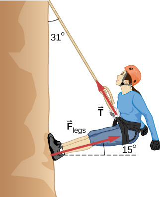
- [openstax univ. phys. vol. 1 – 6.61] Consider the 52.0-kg mountain climber shown below.
- Find the tension in the rope and the force that the mountain climber must exert with her feet on the vertical rock face to remain stationary. Assume that the force is exerted parallel to her legs as shown.
- What minimum coefficient of static friction between her shoes and the cliff is needed to prevent her feet from sliding against the rock?
- [openstax univ. phys. vol. 1 – 6.77] A car rounds an unbanked curve of radius 65.0 m. The coefficient of static friction between the road and the tires is 0.700. What is the maximum speed at which the car can traverse the curve without slipping?
- [openstax univ. phys. vol. 1 – 6.67(modified)] What is the ideal banking angle for a gentle turn of a 1.20 km radius on a highway with a 105 km/h speed limit (about 65 mi/h) so that when a car is traveling at the speed limit it can safely make the turn even when the road is icy and there is no friction?

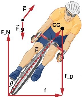
- [openstax univ. phys. vol. 1 – 6.70(modified)] Part of riding a bicycle involves leaning at the correct angle when making a turn, as seen below. To be stable, the force exerted by the ground must be on a line going through the center of gravity. The force on the bicycle wheel can be resolved into two perpendicular components—friction parallel to the road and the vertical normal force. Calculate θ for a 12.0 m/s turn of radius 30.0 m (as in a race).
- [openstax univ. phys. vol. 1 – 6.73-modified] A child of mass 40.0 kg is in a roller coaster car that travels in a loop of a radius of 7.00 m. At point A the speed of the car is 10.0 m/s, and at point B, the speed is 10.5 m/s. Assume the child is not holding on and does not wear a seat belt.
- What is the force of the car seat on the child at point A?
- What is the force of the car seat on the child at point B?


