Electric Charges In Motion
Last Update: 07/01/2022
Resistors in series and parallel
resistors in series
Resistors are in series when they are connected back to back and the same current flows through them. The left part of the Figure 25.1 shows resistors R1, R2, and R3 in series and connected to a battery.

The equivalent resistance of the three resistors would have the same voltage as the combined voltages of the three resistors and therefore experience the same current passing through it. The equivalent resistance is shown as Req on the right in Figure 25.1. In this section, we will derive an expression for the equivalent resistance of resistors in series.
To find the relationship between the voltages, remember that voltage is like the difference in elevation. The positive terminal of the battery is at the highest potential or highest elevation, and the negative terminal is at the lowest potential or elevation. As we go from positive to the negative terminal, we have to take steps down as we go across each resistor. This is all demonstrated in Figure 25.2.

Referring to Figure 25.2 we see that

For each resistor, the relationship between voltage, current, and resistance is  or
or  . Note that the same current flows through all three resistors, and that the same current must also flow through the equivalent resistor, Req. Therefore, we can rewrite the equation above as

Dividing both sides by current, I, yields

This result can be generalized for any number of resistors in series.
 Resistors In Series
Example 25.1
Suppose the voltage across the battery in Figure 25.1 is 12.0 V, and the resistances are R1=1.00Ω, R2=6.00Ω, and R3=13.0Ω.
(a) What is the total resistance?
(b) Find the current in each resistor.
(c) Calculate the voltage drop in each resistor, and show these add to equal the voltage across the battery.
(d) Calculate the power dissipated by each resistor.
(e) Find the power output of the battery, and show that it equals the total power dissipated by the resistors.
Solution for (a)
The resistors are in series. Therefore


Solution for (b)
The current in each resistor is the same as the current in the equivalent resistor. Let’s apply Ohm’s Law to the equivalent resistor to find the current.


Solution for (c)
The voltage drop across each resistor can be calculated using Ohm’s Law for that resistor. Notice that the same current or 0.600A goes through all resistors.

|

|

|


If we add these voltages, we get the voltage across the battery, as expected.

Solution for (d)
For an ohmic device

We can use any one of these equations to determine the power dissipated in each resistor.

|

|

|


Solution for (e)
The power of any electrical device, including a battery can be calculated with


The output power of the battery is equal to the sum of the power dissipated in all resistors.

resistors in parallel
Figure 25.3(a) shows three resistors in parallel, wired to a battery. Resistors are in parallel when each resistor is connected directly to the voltage source by connecting wires having negligible resistance. Each resistor thus has the full voltage of the source applied to it.
 |
 |
In this section, we find an expression for the equivalent resistance of resistors connected in parallel.
The voltage across each resistor is the same as the voltage across the battery.

Applying Ohm’s Law for each resistor we get
 |
 |
 |
Conservation of charge dictates that the current passing through the battery must equal the sum of the currents going through the resistors. If we were to replace the three resistors with an equivalent resistance, the current passing through that resistor would be equal to the current going through the battery, as shown in Figure 25.3(b).

Replacing I with ΔV/R for each resistor, we get

Dividing both sides byΔV yields

This result can be generalized to any number of resistors.
 Resistors In Parallel
Example25.2
Let the voltage output of the battery equal to 12.0V and resistances in the parallel connection in Figure 25.3 be the same as the previously considered. R1=1.00Ω, R2=6.00Ω, and R3=13.0Ω.
(a) What is the equivalent resistance?
(b) Find the current going through the battery.
(c) Calculate the currents in each resistor, and show these add to equal the total current output of the source.
(d) Calculate the power dissipated by each resistor.
(e) Find the power output of the source, and show that it equals the total power dissipated by the resistors.
Solution for (a)
The equivalent resistance of resistors in parallel is


Solution for (b)
The current going through the battery is equal to the current going through the equivalent resistor.


Solution for (c)
We can use Ohm’s law to determine the current in each resistor.
|
|
|
|


The sum of these currents is equal to the current that passes through the battery.

With three significant figures, this is 14.9A, as expected.
Solution for (d)
For an ohmic device
We can use either one of these equations to determine the power dissipated in each resistor.
|
|
|
|


Solution for (e)
The output power of the battery is


The output power of the battery is equal to the sum of the power dissipated in all resistors.

With three significant figures, this is 179W, as expected.
Discussion
Notice that when resistors are connected in parallel, the equivalent resistance is always less than the smallest resistor.
terminal voltage and internal resistance
When you forget to turn off your car lights, they slowly dim as the battery runs down. Why don’t they simply blink off when the battery’s energy is gone? Their gradual dimming implies that battery output voltage decreases as the battery is depleted.
Furthermore, if you connect an excessive number of 12-V lights in parallel to a car battery, they will be dim even when the battery is fresh and even if the wires to the lights have very low resistance. This implies that the battery’s output voltage is reduced by the overload.
The reason for the decrease in output voltage for depleted or overloaded batteries is that all voltage sources have two fundamental parts—a source of electrical energy and internal resistance. Let us examine both.
Source of Electrical Energy – EMF ( )
)
The emf (electromotive force) is the potential difference of a battery when no current is flowing through it. Units of emf are volts. In this text, the symbols “emf”, ““, and “E” all represent the electromotive force of the battery in volts.
Emf depends on the mechanism used to generate energy, such as the particular combination of chemicals in a battery. However, emf differs from the voltage output of the device when current flows. The voltage across the terminals of a battery is less than the emf when current flows through the battery, and it declines further as the battery is depleted or loaded down. However, if the device’s output voltage can be measured without drawing current, then the output voltage will equal emf (even for a very depleted battery).
Internal Resistance
Internal resistance is the inherent resistance to the flow of current within the battery itself.
Figure 25.4 is a schematic representation of the two fundamental parts of any voltage source. The emf (represented by E in the figure) and internal resistance, r, are in series. The smaller the internal resistance for a given emf, the more current and the more power the source can supply.

The internal resistance, r, increases as the battery is depleted.
Terminal Voltage
The voltage output of a device is measured across its terminals and, thus, is called the terminal voltage. Terminal voltage is given by
 Terminal Voltage Of A Battery
where is the emf, r is the internal resistance and I is the current flowing at the time of the measurement.
You can see that the larger the current, the smaller the terminal voltage. And it is likewise true that the larger the internal resistance, the smaller the terminal voltage.
Suppose a battery is supplying power to some electrical device, often called the load. The resistance of the device is the load resistance, Rload. This is demonstrated in Figure 25.5. Since the internal resistance of the battery, r, and the resistance of the device, Rload, are in series, the total resistance in the circuit is Rload + r. Thus the current is given by Ohm’s law to be

As batteries are depleted, the internal resistance,r, increases. If r becomes a significant fraction of the load resistance, then the current is significantly reduced, as the following example illustrates.
Example 25.3
A certain battery has a 12.0-V emf and an internal resistance of 0.100Ω.
(a) Calculate its terminal voltage when connected to a 10.0Ω load.
(b) What is the terminal voltage when connected to a 0.500Ω load?
Solution to (a)
The 10.0 Ω load and the internal resistance, 0.100Ω, are connected in series. Therefore the current in the circuit is


The terminal voltage of the battery is


Solution for (b)
Repeating the same approach as (a) we get


The terminal voltage of the battery is


Discussion
Notice that when internal resistance of the battery is comparable in size to the load resistance, the terminal voltage becomes significantly smaller than the emf of the battery.
kirchhoff’s rules
Many complex circuits, such as the one in Figure 25.6, cannot be analyzed with the series-parallel techniques. There are, however, two circuit analysis rules that can be used to analyze any circuit, simple or complex. These rules are based on the laws of conservation of charge and conservation of energy. The rules are known as Kirchhoff’s Junction Rule and Loop Rule.

Kirchhoff’s Junction rule
Kirchhoff’s junction rule states that the sum of all currents entering a junction must equal the sum of all currents leaving the junction.
The junction rule is an application of the conservation of charge to a junction; it is illustrated in Figure 25.7. Current is the flow of charge, and the charge is conserved; thus, whatever charge flows into the junction must flow out. Kirchhoff’s first rule requires that I1=I2+I3 (see figure). Equations like this can and will be used to analyze circuits and to solve circuit problems.

kirchhoff’s loop rule
Kirchhoff’s loop rule states that the algebraic sum of changes in potential around any closed circuit path (loop) must be zero.
The loop rule is an application of conservation of energy. The loop rule is stated in terms of potential, V, rather than potential energy, but the two are related since U=qV. Recall that emf is the potential difference of a source when no current is flowing. In a closed loop, whatever energy is supplied by emf must be transferred into other forms by devices in the loop, since there are no other ways in which energy can be transferred into or out of the circuit. Figure 25.8 illustrates the changes in potential in a simple series circuit loop.

Figure 25.8(a) is a standard schematic of a simple series circuit. The emf supplies 18 V, which is reduced to zero by the resistances, with 1 V across the internal resistance, and 12 V and 5 V across the two load resistances, for a total of 18 V. Figure 25.8(b) represents the potential as elevation, where a charge is raised in potential by the emf and lowered by the resistances.
Kirchhoff’s loop rule requires emf-Ir-IR1-IR2=0.
applying kirchhoff’s Rules
By applying Kirchhoff’s rules, we generate equations that allow us to find the unknowns in circuits. The unknowns may be currents, emf’s, or resistances. Each time a rule is applied, an equation is produced. If there are as many independent equations as unknowns, then the problem can be solved. There are two decisions you must make when applying Kirchhoff’s rules. These decisions determine the signs of various quantities in the equations you obtain from applying the rules.
- When applying Kirchhoff’s junction rule, you must label the current in each branch and decide in what direction it is going. There is no risk here, for if you choose the wrong direction, the current will be of the correct magnitude but negative.
- When applying Kirchhoff’s loop rule, you must identify a closed loop and decide in which direction to go around it, clockwise or counterclockwise. For example, in Figure 25.8 the loop was traversed in the same direction as the current. Again, there is no risk; going around the circuit in the opposite direction reverses the sign of every term in the equation, which is like multiplying both sides of the equation by -1.
Figure 25.9 and the following points will help you get the plus or minus signs right when applying the loop rule. Note that the resistors and emfs are traversed by going from a to b. In many circuits, it will be necessary to consider more than one loop. In traversing each loop, one needs to be consistent for the sign of the change in potential. (See Example 25.4.)

- When a resistor is traversed in the same direction as the current, the change in potential is -IR
- When a resistor is traversed in the direction opposite to the current, the change in potential is +IR
- When an emf is traversed from <span id="MathJax-Element-5602-Frame" class="MathJax" style="font-style: normal;font-weight: normal;line-height: normal;font-size: 14px;text-indent: 0px;text-align: left;text-transform: none;letter-spacing: normal;float: none;direction: ltr;max-width: none;max-height: none;min-width: 0px;min-height: 0px;border: 0px;padding: 0px;margin: 0px" role="presentation" data-mathml="“>– to + (the same direction it moves positive charge), the change in potential is +emf.
- When an emf is traversed from + to <span id="MathJax-Element-5603-Frame" class="MathJax" style="font-style: normal;font-weight: normal;line-height: normal;font-size: 14px;text-indent: 0px;text-align: left;text-transform: none;letter-spacing: normal;float: none;direction: ltr;max-width: none;max-height: none;min-width: 0px;min-height: 0px;border: 0px;padding: 0px;margin: 0px" role="presentation" data-mathml="“>– (opposite to the direction it moves positive charge), the change in potential is -emf.
Example 25.4
Find the currents flowing in the circuit in Figure 25.10.

This circuit is sufficiently complex that the currents cannot be found using Ohm’s law and the series-parallel techniques—it is necessary to use Kirchhoff’s rules. Currents have been labeled I1, I2, and I3 in the figure and assumptions have been made about their directions. Locations on the diagram have been labeled with letters a through h. In the solution we will apply the junction and loop rules, seeking three independent equations to allow us to solve for the three unknown currents.
Solution
We begin by applying Kirchhoff’s junction rule at point a. This gives

since I1 flows into the junction, while I2 and I3 flow out. Applying the junction rule at e produces exactly the same equation so that no new information is obtained. This is a single equation with three unknowns—three independent equations are needed, and so the loop rule must be applied.
Now we consider the loop abcdea. Going from a to b, we traverse R2 in the same (assumed) direction of the current I2, and so the change in potential is -I2R2. Then going from b to c, we go from – to + so that the change in potential is +emf. Traversing the internal resistance r1 from c to d gives -I2r1. Completing the loop by going from d to a again traverses a resistor in the same direction as its current, giving a change in potential of -I1R1.
The loop rule states that the changes in potential sum to zero. Thus,


Substituting values from the circuit diagram for the resistances and emf, and canceling the ampere unit gives

Now applying the loop rule to aefgha (we could have chosen abcdefgha as well) similarly gives


Note that the signs are reversed compared with the other loop, because elements are traversed in the opposite direction. With values entered, this becomes

These three equations are sufficient to solve for the three unknown currents. First, solve the second equation for I2.

Now solve the third equation for I3.

Substituting these two new equations into the first one allows us to find a value for I1.


Substituting this value forI_1 back into gives


The minus sign means I2 flows in the direction opposite to that assumed in Figure 25.10.
Finally, substituting the value forI1 into gives


Discussion
Just as a check, we note that indeed  . The results could also have been checked by entering all of the values into the equation for the abcdefgha loop.
Attribution
This chapter contains material taken from Openstax College Physics -Introduction to Circuits and DC Instruments, and is used under a CC BY 4.0 license. Download these books for free at Openstax
To see what was changed, refer to the List of Changes.
problems
- [openstax univ. phys. vol.2 – 10.26]Find the equivalent resistance of three resistors with values 0.100kΩ, 2.50kΩ, and 4.00kΩ
- when they are connected in series.
- when they are connected in parallel.
- [openstax univ. phys. vol. 2 – 10.29] Your car’s 30.0-W headlight and 2.40-kW starter are ordinarily connected in parallel to a 12.0-V battery. What power would one headlight and the starter consume if they were connected in series?
- [openstax univ. phys. vol. 2 – 10.30] A 48.0-V battery is connected to a 24.0Ω and a 96.0Ω resistors. Find the current through each resistor, the current through the battery, the power dissipated by each resistor, and the power delivered by the battery
- when the resistors are connected in series.
- when the resistors are connected in parallel.
- Consider the circuit shown below. The terminal voltage of the battery is 18.0V.
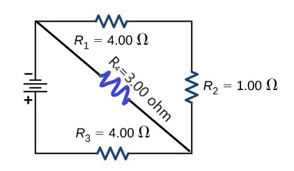
- Find the equivalent resistance of the circuit.
- Find the current and voltage for each resistor.
- Find the power dissipated by each resistor.
- Find the power supplied by the battery.
- [openstax college physics-21.17] A large carbon-zinc dry cell with an emf of 1.54-V is used in a physics lab to supply 2.00 A to a circuit. The internal resistance of the dry cell is 0.100Ω.
- Find the terminal voltage of the cell.
- How much electrical power does the cell produce?
- What power goes to its load (the external circuit connected to the cell?
- [openstax college physics- 21.16]What is the output voltage of a 3.0000-V lithium cell in a digital wristwatch that draws 0.300 mA, if the cell’s internal resistance is2.00Ω.
- [openstax college physics-21.25] The terminal voltage of a voltage source drops by 2.00 V when the current supplied is increased by 5.00 A?
- What is the internal resistance of the voltage source?
- Can the emf of the voltage source be found with the information supplied?
- [openstax college physics 21.4] An 1800-W toaster, a 1400-W electric frying pan, and a 75.0-W lamp are plugged into the same outlet in a 15.0-A, 120-V circuit. (The three devices are in parallel when plugged into the same socket.
-
- What current is drawn by each device?
- Will this combination blow the 15.0-A fuse?
-
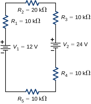
- [openstax univ. phys. vol. 2 – 10.36]Consider the circuit shown below.
-
- Find the voltage across each resistor.
- What is the power supplied to the circuit by the batteries, and the power dissipated or consumed by the circuit?
-
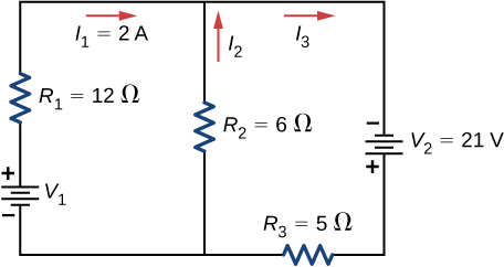
- [openstax univ. phys. vol. 2 – 10.30]Consider the circuit shown below. Find V1, I2, and I3.
- In the circuit below, the voltage of the battery is 24.0V. Find the voltage and current in each resistor. Use 3 significant figures for all the known quantities.


