Geometrical Optics
Last Update: 07/12/2022
In this unit we discuss image formation by flat (plane) mirrors, as well as spherical mirrors. We can define two general types of spherical mirrors. If the reflecting surface is the outer side of the sphere, the mirror is called a convex mirror. If the inside surface is the reflecting surface, it is called a concave mirror.

The symmetry axis of such optical elements is called the principal axis. For a spherical mirror, the principal axis passes through the mirror’s center of curvature and the mirror’s vertex, as shown in Figure 29.0.
flat(plane)mirrors
Figure 29.1 is a ray diagram that helps illustrate how a flat mirror forms an image. Two rays are shown emerging from the same point on the object, striking the mirror, and being reflected such that the angle of reflection is equal to the angle of incidence. When we look at the mirror, our eyes receive these reflected rays. Our brain is wired such that we perceive the two rays coming from their point of intersection. In order to find that intersection point, we have to extend the reflected rays behind the mirror. Wherever the extensions of the two reflected rays meet is the image of the point from which the incident rays originated. This image is virtual because it is formed by the extension of the reflected rays. A virtual image cannot be projected onto a screen and appears to be behind the mirror. Using the fact that the angle of reflection equals the angle of incidence we can use geometry to prove that the image and object are the same distance from the mirror and that the size of the image is also equal to the size of the object.

When dealing with mirrors, distances that are on the reflective side of the mirror are positive, and distances that are behind the mirror are negative. Furthermore, the object’s distance from the mirror is denoted with do and the image’s distance from the mirror is di. The height of the object is ho, and the height of the image is hi.
In summary, the image characteristics of a plane mirror are the following:
- Image is virtual
- di=-do
- hi=ho
Two mirrors at right angles form three images, as shown in Figure 29.2(a). Images 1 and 2 result from rays that reflect from only a single mirror, but Image 1,2 is formed by rays that reflect from both mirrors. This is shown in the ray-tracing diagram in Figure 29.2(b). To find Image 1,2, you have to look behind the corner of the two mirrors. Notice that Image 1,2 is the image of Image 1 formed by mirror 2. Image 1,2 is also the image of Image 2 formed by mirror 1. When the angle between the two mirrors is 90°, these two additional images coincide, and altogether three images are visible in the two mirrors as shown below. As the angle between the mirrors is decreased, these additional images separate resulting in multiple images in the two mirrors.

spherical concave mirrors
Parallel rays of light that strike the surface of a spherical concave mirror follow the law of reflection. For a mirror that is large compared with its radius of curvature, as in Figure 29.3(a), we see that the reflected rays do not cross at the same point, and the mirror does not have a well-defined focal point. But a spherical concave mirror that is small compared with its radius of curvature, as shown in Figure 29.3(b), to a very good approximation, has a well-defined focal point at F. The distance between the focal point and the center of the mirror is the focal length, f.

In this text, we will only discuss image formation by spherical mirrors that have a well-defined focal point.
The radius of curvature, R, of a spherical mirror, is the radius of the imaginary circle that the mirror is part of. It can be shown that for spherical mirrors
 Focal Length Of Spherical Mirrors
Law of Reflection dictates the following general rules about how light reflects from a concave mirror. The rays described below can be used to construct a ray diagram to locate images formed by a concave mirror and to determine the images’ characteristics.
Ray Diagram For Concave Mirrors
- A ray approaching a concave mirror parallel to its axis is reflected through the focal point F of the mirror on the same side. (See rays 1 in Figure 29.4, and Figure 29.5)
- A ray approaching a concave mirror through its focal point is reflected parallel to its axis. (See ray 2 in Figure 29.4 and ray 3 in Figure 29.5)
- A ray approaching a concave mirror through its center of curvature, C, reflects back onto itself. (See ray 3 in Figure 29.4)
- Any ray striking the center of a mirror is reflected as dictated by the law of reflection; it makes the same angle with the axis when leaving as when approaching. (See ray 4 in Figure 29.4 and ray 2 in Figure 29.5.)

An image that is formed by the intersection of reflected rays on the reflective side of the mirror can be projected on a screen and is a real image. The image in Figure 29.4 is a real image.
An image that is formed by the extension of the reflected rays on the back side of the mirror cannot be projected on a screen and is a virtual image.
 |
 |
Figure 29.5 shows how a virtual image is formed by a concave mirror. Notice that the reflected rays had to be extended behind the mirror (dashed lines) to find their point of intersection. In general, for a concave mirror, if the object is closer to the mirror than the focal point (do<f ) the image is virtual. Figure 29.6 shows the virtual image of the person’s face behind the mirror. As demonstrated in Figure 29.4 and Figure 29.5, a concave mirror can form both a real and a virtual image.
Geometry can be used to prove the following relationship between the object distance, the image distance, and the focal length of a spherical mirror.
 Mirror Equation
In this equation
 is the distance between the object and the mirror
 is the distance between the image and the mirror
 is the focal length of the mirror
Sign Convention For Mirrors
- Distances on the reflective side of the mirror are positive.
- Distances behind the mirror are negative.
- The focal length of a concave mirror is positive
- The focal length of a convex mirror is negative
Lateral magnification is the ratio of the height of the image, hi, over the height of the object, ho. With geometry it can be shown that
 Lateral Magnification
If either the object or the image is right side up, its height is positive, if it is upside down, its height is negative. Therefore
M>0 ⇒ image is right side up relative to the object.
M<0 ⇒ image is upside down relative to the object.
|M|>1 ⇒ image is magnified
|M|<0 ⇒ image is reduced
Example 29.1
A concave mirror has a radius of curvature of 8.00cm. Determine the location of the image and its characteristics if the object is located
a) 12.0cm from the mirror.
b) 6.00cm from the mirror.
c) 2.00cm from the mirror.
In each case draw a ray diagram to scale to confirm your calculations.
The solution to part (a)
the focal length of the mirror can be found from its radius of curvature.


Notice that the focal length of a concave mirror is positive. Now we can use the mirror equation to calculate the distance between the image and the mirror.


Since d_i>0 we expect an image on the reflective side of the mirror or a real image.
To describe the other image characteristics we need to calculate the magnification.


A negative magnification means the image is upside down. And since |M|<1, the image is reduced.
The ray diagram below confirms these findings.

The solution to part (b)
Using the same process as in (a) we get


A positive di means a real image on the reflective side of the mirror.


A negative magnification means the image is upside down. And since |M|>1, the image is magnified.
These agree with the ray diagram below.

Solution for part (c)
The approach is the same as in (a) and (b)


A negative di means the image is formed behind the mirror and is virtual.


A positive magnification means the image is right-side up. And since |M|>1, the image is magnified.
These agree with the ray diagram below.

spherical convex mirrors
The convex mirror shown in Figure 29.10 also has a focal point. Parallel rays of light reflected from the mirror seem to originate from the point F at the focal distance, f, behind the mirror. Since the center of curvature, C, and the focal point, F, of a convex mirror are on the back side, the radius of curvature and focal length of a convex mirror are both negative. R<0, f<0, and f=R/2.

Ray Diagram for Convex Mirrors
- A ray approaching a convex mirror parallel to its axis is reflected through the focal point F of the mirror on the back side. (See rays 1 in Figure 29.11)
- A ray approaching a convex mirror through its focal point is reflected parallel to its axis. (See ray 2 in Figure 29.11)
- A ray approaching a convex mirror through its center of curvature, C, reflects back onto itself. (See ray 3 in Figure 29.11)
- Any ray striking the center of a mirror is reflected as dictated by the law of reflection; it makes the same angle with the axis when leaving as when approaching. (See ray 4 in Figure 29.11)

The image formed by a convex mirror is always virtual, upright, and reduced, regardless of the location of the object.
 |
 |
The equations used to analyze image formation by convex mirrors are the same as the ones for concave mirrors.
Mirror Equation
Lateral Magnification
Example 29.2
A convex mirror has a radius of curvature of 8.00cm. Determine the location of the image and its characteristics if the object is located 6.00cm from the mirror. Draw a ray diagram to scale to confirm your calculations.
Solution
The radius of curvature and focal length of a convex mirror are negative.


Now we can use the mirror equation to calculate the distance between the image and the mirror.


Since  we expect an image on the back side of the mirror or a virtual image.
To describe the other image characteristics we need to calculate the magnification.


Since M>0 we conclude the image is upright.
Since |M|<1 we conclude the image is reduced.
A ray diagram that is drawn to scale confirms these calculations.

Notice in this ray diagram, the reflective side is on the right.
Attribution
This chapter contains material taken from Openstax College Physics – Geometric Optics, and Openstax University Physics Volume 3-Geometric Optics and Image Formation, and are used under a CC BY 4.0 license. Download these books for free at Openstax
To see what was changed, refer to the List of Changes.
problems
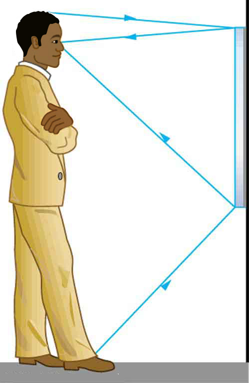
- [openstax college phyiscs-25.1]Suppose a man stands in front of a mirror as shown below. His eyes are 1.65 m above the floor, and the top of his head is 0.130 m higher. Find the height above the floor of the top and bottom of the smallest mirror in which he can see both the top of his head and his feet. How is this distance related to the man’s height?
- [openstax univ. phys. vol.3 – 2.29] The following figure shows a light bulb between two spherical mirrors. One mirror produces a beam of light with parallel rays; the other keeps light from escaping without being put into the beam. Where is the filament of the light in relation to the focal point or radius of curvature of each mirror?

- [openstax univ. phys. vol. 3 – 2.36(modified)] A shopper standing 3.00 m from a convex security mirror sees his image with a magnification of 0.250.
- Find the location of the image?
- What are the focal length and the radius of curvature of the mirror?
- Construct a ray diagram to scale to verify your calculations.
- [openstax univ. phys. vol. 3 – 2.37] An object 1.50 cm high is held 3.00 cm from a person’s cornea, and its reflected image is measured to be 0.167 cm high. The cornea is the transparent part of the eye that covers the iris and the pupil and allows light to enter the eye.
- What is the magnification?
- Where is the image formed?
- Find the radius of curvature of the cornea. (This technique is used by optometrists to measure the curvature of the cornea for contact lens fitting. The instrument used is called a keratometer, or curve measurer.)
- [openstax univ. phys. vol. 3 – 2.35(modified)] When a person’s face is 12.0cm away from a makeup mirror she can see her image in the mirror magnified 1.50 times. What is the focal length of the makeup mirror? Construct a ray diagram to scale to verify your calculations.
- A concave mirror has a focal length of 15.0cm. A 4.00cm tall object is placed in front of the mirror. In each case determine the location of the image and its characteristics.
- The object is placed 40.0cm in front of the mirror.
- The object is placed 30.0cm in front of the mirror.
- The object is placed 15.0cm in front of the mirror.
- The object is placed 5.00cm in front of the mirror.
- When an object is placed 5.00cm in front of a spherical mirror, a virtual image of magnification +3.00 is produced. Find the radius of curvature of this mirror and indicate whether it is concave or convex.
- A 3.00cm tall object is placed 12.0cm in front of a mirror. The image produced is 9.00cm tall and upright.
- What is the focal length of this mirror?
- Is this a concave or convex mirror?
- Draw a ray diagram to scale to verify your calculations.


