Wave Optics
Last Update: 07/08/2022
electromagnetic waves
We can get a good understanding of electromagnetic waves (EM) by considering how they are produced. Whenever a current varies, associated electric and magnetic fields vary, moving out from the source like waves. Perhaps the easiest situation to visualize is a varying current in a long straight wire, produced by an AC generator at its center, as illustrated in Figure 28.1.

The changing electric field propagates outward at the speed of light. There is an associated magnetic field, B, which propagates outward as well. As shown in Figure 28.2(a) The current in the antenna produces the circular magnetic field lines. The current produces the separation of charge along the wire, which in turn creates the electric field as shown. In Figure 28.2(b), the electric and magnetic fields, E and B, near the wire are perpendicular; they are shown here for one point in space. In Figure 28.2(c), the magnetic field varies with current and propagates away from the antenna at the speed of light.

The electric and magnetic waves are shown together at one instant in time in Figure 28.3. The electric and magnetic fields produced by a long straight wire antenna are exactly in phase. Note that they are perpendicular to one another and to the direction of propagation, making this a transverse wave. Electromagnetic waves propagate with the speed of light.

Like any other wave, electromagnetic waves are described in terms of their wavelength, period, frequency, and amplitude. The wavelength, λ (measured in meters), is the distance between two consecutive crests. In other words, the wavelength is the distance the wave travels in one cycle. Period, T (measured in seconds), is the time of one complete oscillation. Frequency, f(measured in hertz Hz=1/s), is the number of oscillations per second. Finally, the amplitude is the height of the wave. The figure below shows how a transverse wave looks as viewed from above and from the side. A light wave can be imagined to propagate like this, although we do not actually see it wiggling through space. From above, we view the wavefronts (or wave crests) as if we were looking down on ocean waves. The side view would be a graph of the electric or magnetic field.

The speed of propagation of any wave is given by

In a vacuum, and very nearly in the air, an electromagnetic wave travels at the speed of light, or c=3.00×10⁸m/s.
 Speed Of Electromagnetic Waves In Vacuum
Figure 28.4 shows how the various types of electromagnetic waves are categorized according to their wavelengths and frequencies—that is, it shows the electromagnetic spectrum. Figure 28.5 illustrates the visible part of the EM spectrum that we call light.


When the light goes from a vacuum to some medium, like water, its speed and wavelength change, but its frequency remains the same. Index of refraction of a medium (like water, glass, etc.), n, is defined as the ratio of the speed of light in vacuum, c, over the speed of light in that medium, v.
 Index Of Refraction
The speed of light depends strongly on the type of material since its interaction with different atoms, crystal lattices, and other substructures vary. Table 28.1 gives the indices of refraction for some representative substances.

Example 28.1
A beam of light with a wavelength of 720nm is shone on a piece of zircon, a material used in jewelry to imitate diamond.
a) Calculate the speed of light in zircon.
b) Determine the wavelength and frequency of light in zircon.
Solution for (a)
According to Table 28.1, the index of refraction of zircon is n=1.923. Given that the speed of light in a vacuum is c=3.00×10⁸m/s, we can find the speed of light in zircon.


Solution for (b)
Let’s find the frequency of this light beam in the air first. Notice that the speed of light in air is practically the same as the speed of light in a vacuum.


Since the frequency of light doesn’t change when light travels from one medium to another medium, the frequency in zircon is also .
With speed and frequency, we can find the wavelength.


The Dutch scientist Christiaan Huygens (1629–1695) developed a useful technique for determining in detail how and where waves propagate. Starting from some known position, Huygens’s principle states that every point on a wavefront is a source of wavelets that spread out in all directions at the same speed as the wave itself. The new wavefront is tangent to all of the wavelets.
Figure 28.6 shows how Huygens’s principle is applied. A wavefront is the long edge that moves, for example, with the crest or the trough. Each point on the wavefront emits a semicircular wave that moves at the propagation speed v. We can draw these wavelets at a time t later so that they have moved a distance s=vt. The new wavefront is a plane tangent to the wavelets and is where we would expect the wave to be a time t later. Huygens’s principle works for all types of waves, including water waves, sound waves, and light waves. It is useful not only in describing how light waves propagate but also in explaining the laws of reflection and refraction.

Reflection
Whenever we look into a mirror or squint at the sunlight glinting from a lake, we are seeing a reflection. Reflection occurs when light bounces off a surface. The angles of the incident and reflected rays are measured relative to a line perpendicular to the surface at the point where the rays strike the surface. This perpendicular line is called the normal line. The law of reflection states that the angle of reflection equals the angle of incidence,  , and that the incident ray, the reflected ray, and the normal line all reside on the same plane. This is demonstrated in Figure 28.7.


 |
 |
A mirror or any other very smooth surface, on the other hand, when illuminated by many parallel rays reflects them in only one direction. This results in only the observer at a particular angle being able to see the reflected light, as shown in Figure 28.10.

When we see ourselves in a mirror, it appears that our image is actually behind the mirror. This is illustrated in Figure 28.11. We see the light coming from a direction determined by the law of reflection. The angles are such that our image is exactly the same distance behind the mirror as we stand away from the mirror.

refraction
The changing of a light ray’s direction (loosely called bending) when it passes through variations in the matter is called refraction.
Figure 28.12 shows how a ray of light changes direction when it passes from one medium to another. As before, the angles are measured relative to a perpendicular to the surface at the point where the light ray crosses it. Some of the incident light will be reflected from the surface, but for now, we will concentrate on the light that is transmitted.

The change in direction of the light ray depends on how the speed of light changes. The change in the speed of light is related to the indices of refraction of the media involved. As mentioned earlier, the index of refraction of a medium is the ratio of the speed of light in a vacuum over the speed of light in that medium, .
In the situations shown in Figure 28.12, medium 2 has a greater index of refraction than medium 1. This means that the speed of light is less in medium 2 than in medium 1. Note that as shown in Figure 28.12(a), the direction of the ray moves closer to the perpendicular when it slows down. Conversely, as shown in Figure 25.12(b), the direction of the ray moves away from the perpendicular when it speeds up. The path is exactly reversible.
The law of refraction can be explained by applying Huygens’s principle to a wavefront passing from one medium to another as shown in Figure 28.13. Each wavelet in the figure was emitted when the wavefront crossed the interface between the media. Since the speed of light is smaller in the second medium, the waves do not travel as far in a given time, and the new wavefront changes direction as shown. This explains why a ray changes direction to become closer to the perpendicular when light slows down.

The amount that a light ray changes its direction depends both on the incident angle and the amount that the speed changes. For a ray at a given incident angle, a large change in speed causes a large change in direction, and thus a large change in angle. The exact mathematical relationship is the law of refraction, or “Snell’s Law,” which is stated in equation form as
 The Law Of Refraction
 is the index of refraction of medium 1
 is the angle the light ray makes with a line perpendicular to the boundary in medium 1.
 is the index of refraction of medium 2
 is the angle the light ray makes with a line perpendicular to the boundary in medium 2.
Example 28.2
Light goes from air to diamond with an incident angle of 30º. Calculate the angle of refraction in the diamond.
Solution
Index of refraction of air is 1 and index of refraction of diamond is given in table 28.1. ndiamond=2.419
Using the law of refraction, we get


total internal reflection
Consider what happens when a ray of light strikes the surface between two materials, such as is shown in Figure 25.13(a). Part of the light crosses the boundary and is refracted; the rest is reflected. If, as shown in the figure, the index of refraction for the second medium is less than for the first, the ray bends away from the perpendicular.
 |
 |
 |
Now imagine what happens as the incident angle is increased. This causes Θ2 to increase also. The largest angle of refraction can be is 90°, as shown in Figure 28.14(b). The critical angle, Θc, for a combination of materials is defined to be the incident angle that produces an angle of refraction of 90°. If the incident angle, Θ1 is greater than the critical angle, as shown in Figure 28.14(c), then all of the light is reflected back into medium 1, a condition called total internal reflection.
Total internal reflection occurs for any incident angle greater than the critical angle, Θc, and it can only occur when the second medium has an index of refraction less than the first.
Example 28.3
What is the critical angle for light traveling in a polystyrene (a type of plastic) pipe surrounded by air?
Solution
The index of refraction of air is 1, and according to Table 28.1, the index of refraction of polystyrene is npolystyrene=1.49. Since total internal reflection only happens when the light goes from a medium with a higher index of refraction to a medium with a lower index of refraction, to find the critical angle we must consider refraction as the light goes from polystyrene to air.

Applying the law of refraction to the refraction shown in Figure 28.15, we get


dispersion
The angle of refraction depends on the index of refraction. We know that the index of refraction depends on the medium. But for a given medium, n also depends on wavelength, as you can see in Table 28.2.

Note that, for a given medium, n increases as wavelength decreases and is greatest for violet light. Thus violet light is bent more than red light, as shown for a prism in Figures 28.16(b) and 28.17. Dispersion is defined as the spreading of white light into its full spectrum of wavelengths. More technically, dispersion occurs whenever there is a process that changes the direction of light in a manner that depends on wavelength.
 |
 |
Example 28.4
A beam of white light goes from air into flint glass at an incidence angle of 43.2°. What is the angle between the red (660 nm) and violet (410 nm) parts of the refracted light?
Solution
We need to find the angle of refraction for each wavelength, and then find the difference between them.

From Table 28.2 we see that the index of refraction of flint glass for red light with a wavelength of 660nm is nred=1.662. Applying the law of refraction we get


From Table 28.2 we see that the index of refraction of flint glass for violet light with a wavelength of 410nm is nviolet=1.698. Applying the law of refraction we get


The angle between the red and violet rays inside the flint glass is


Attribution
This chapter contains material taken from Openstax College Physics -Wave Optics, Openstax College Physics – Geometric Optics, and Openstax University Physics Volume 3-The Nature of Light, and are used under a CC BY 4.0 license. Download these books for free at Openstax
To see what was changed, refer to the List of Changes.
problems
- [openstax univ. phys. vol.3 – 1.26 and 1.27] What is the speed of light in water? In glycerine? In crown glass?
- [openstax univ. phys. vol. 3-1.31] Components of some computers communicate with each other through optical fibers having an index of refraction n=1.55. What time in nanoseconds is required for a signal to travel 0.200 m through such a fiber?
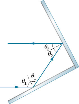
- [openstax univ. phys. vol. 3-1.35] Show that when light reflects from two mirrors that meet each other at a right angle, the outgoing ray is parallel to the incoming ray, as illustrated below.
- [openstax univ. phys. vol. 3-1.44 and 1.45] A scuba diver training in a pool, 2.00m below the surface, looks at his instructor. The angle between the ray in the water and the normal line is 25.0º. The instructor is standing 2.00m away from the normal line, as shown in the figure below.
- What angle does the ray from the instructor’s face make with the normal line at the point where the ray enters?
- Find the height of the instructor’s head above the water.
- Find the apparent depth of the diver’s head below water as seen by the instructor.

- [openstax univ. phys. vol. 3-1.39] A light beam in the air is incident on the surface of a pond, making an angle of 20.0º with respect to the surface. What are the angles of reflection and refraction?
- [openstax univ. phys. vol.3-1.47-modified] Zircon is a gemstone with an index of refraction of 1.923.
- Find the critical angle for the boundary between Zircon and air.
- Draw a diagram to show the critical angle, the refracted ray, and label the media as Zircon and air.
- [openstax univ. phys. vol. 3-1.51] You can determine the index of refraction of a substance by determining its critical angle.
- What is the index of refraction of a substance that has a critical angle of 68.4º when submerged in water?
- What is the substance?
- What would the critical angle be for this substance in the air?
- [openstax univ. phys. vol. 3-1.55] A beam of white light goes from air into water at an incident angle of 75.0º. At what angles are the red (660 nm) and violet (410 nm) parts of the light refracted?
- [openstax univ. phys. vol. 3-1.57] A narrow beam of light containing yellow (580 nm) and green (550 nm) wavelengths goes from polystyrene to air, striking the surface at a 30.0º incident angle.
- What is the angle between the colors when they emerge?
- How far would they have to travel to be separated by 1.00 mm?
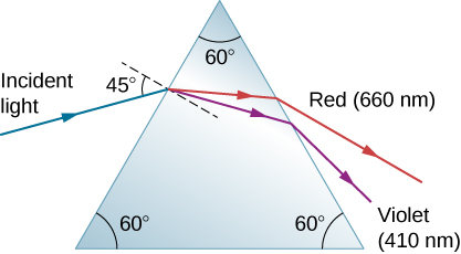
- [openstax univ. phys. vol. 3-1.61] A narrow beam of white light enters a prism made of crown glass at a 45.0º incident angle, as shown below. At what angles, θR, and θv, do the red (660 nm) and violet (410 nm) components of the light emerge from the prism?