Geometrical Optics
Last Update: 06/04/2020
the human eye
Figure 31.1 shows the basic anatomy of the eye. The cornea and lens form a system that, to a good approximation, acts as a single thin lens. For clear vision, a real image must be projected onto the light-sensitive retina, which lies a fixed distance from the lens. The flexible lens of the eye allows it to adjust the radius of curvature of the lens to produce an image on the retina for objects at different distances. The center of the image falls on the fovea, which has the greatest density of light receptors and the greatest acuity (sharpness) in the visual field. The variable opening (i.e., the pupil) of the eye, along with chemical adaptation, allows the eye to detect light intensities from the lowest observable to 1010 times greater (without damage). This is an incredible range of detection. The processing of visual nerve impulses begins with interconnections in the retina and continues in the brain. The optic nerve conveys the signals received by the eye to the brain.

The biggest change in the index of refraction, which is where the light rays are most bent, occurs at the air-cornea interface rather than at the aqueous humor-lens interface. The cornea, which is itself a converging lens with a focal length of approximately 2.3 cm, provides most of the focusing power of the eye. The lens, which is a converging lens provides the finer focus needed to produce a clear image on the retina. The cornea and lens can be treated as a single thin lens. The image formed is much like the one produced by a single converging lens (i.e., a real, inverted image). Although images formed in the eye are inverted, the brain inverts them once more to make them seem upright.
As noted, the image must fall precisely on the retina to produce clear vision—that is, the image distance di must equal the lens-to-retina distance. Because the lens-to-retina distance does not change, the image distance di must be the same for objects at all distances. The ciliary muscles adjust the shape of the eye lens for focusing on nearby or far objects. By changing the shape of the eye lens, the eye changes the focal length of the lens. This mechanism of the eye is called accommodation. Accommodation is shown in Figure 31.2. In Figure 31.2(a), the eye is looking at an object that is far away, the ciliary muscles are totally relaxed and the eye lens is as thin as possible. Under these conditions, a normal eye can focus the image of a very far object on the retina. In Figure 31.2(b), the eye is looking at an object that is close, the ciliary muscles contract, causing the eye lens to bulge and making it more powerful. A normal eye can focus the image of an object as close as 25cm on the retina.

The nearest point an object can be placed so that the eye can form a clear image on the retina is called the near point of the eye. Similarly, the far point is the farthest distance at which an object is clearly visible. A person with normal vision can see objects clearly at distances ranging from 25 cm to essentially infinity. The near point increases with age, becoming several meters for some older people. In this text, we consider the near point to be 25 cm, and the far point to be at infinity.
Vision Correction
In this section, we discuss how corrective lenses can be used to correct nearsightedness and farsightedness.
Nearsightedness, or myopia, is the ability to see near objects, whereas distant objects are blurry. There are two major causes of myopia. One is that the eye lens, in its relaxed state, is too strong. The other reason is an eyeball that is too long. In both cases, light coming from a far away object focuses in front of the retina, as shown in Figure 31.3.

To correct myopia, a diverging lens must be placed in front of the eye, as shown in Figure 31.4.

The distance to the farthest object that can be seen clearly is called the far point of the eye. The far point of the normal eye is infinity.
Farsightedness, or hyperopia, is the ability to see far objects clearly, whereas near objects are blurry. A farsighted eye does not sufficiently converge the rays from a near object to make the rays meet on the retina. This could be either the result of an eye lens that is too weak or an eyeball that is too short, as demonstrated in Figure 31.5.

To correct hyperopia, a converging lens must be placed in front of the eye, as shown in Figure 31.6.

Since the corrective lens is placed in front of the eye lens, we need to understand how an image is formed in a two-lens system. The fundamental idea in analyzing a two-lens system is to realize that the image formed by the first lens acts as an object for the second lens. This is illustrated in the ray diagram in Figure 31.7.

The following examples demonstrate how we can determine the focal length, and therefore the power of the lens needed to correct myopia and hyperopia.
Example 31.1
The farthest distance that a nearsighted person can see clearly is 35.0 cm. What power of corrective contact lens is needed to correct her vision?
Solution
If an object is placed 35.0cm from the eyes, this person can see that object clearly. But if the object is farther away, the image becomes blurry. We want to correct this so that when the object is infinitely far away, the image stays clear. So, we need a corrective lens that can create an image of an object that is infinitely far away, at exactly 35.0cm from the person’s eyes. This image acts as an object for the eye lens, and the eye lens creates a clear image of it on the retina.
Applying the thin lens equation for the contact lens, we set do=∞, di=-35.0cm. Notice that since the image formed by the contact lens is on the same side as the object, this image is virtual and therefore di<0.


To find the power, we need to express the focal length in meters.


A negative power means the lens has to be a diverging lens, as expected.
Discussion
In this problem, we determined the power of contact lenses needed to correct myopia. Since the contact lens is placed right over the eye lens, we didn’t need to make any adjustment for distances. If we were to determine the power of eyeglasses needed to correct this person’s vision, then we had to take into account the distance between the lens of the glasses and the eye lens, when applying the thin lens equation.
Example 31.2
A farsighted person has to hold a book 40.0cm from his eyes in order to be able to see the print. What power of contact lenses are needed to correct his vision?
Solution
Normal eyes have a near point of 25cm. So, we want to determine the power of contact lenses that would allow this person to read comfortably while holding the book 25cm away from his eyes. Since the eye lens can create a focused image on the retina when the object is 40.0cm away, we need a lens that creates an image 40.0cm away from the eye, when the object is placed 25.0cm from the eye.
Applying the thin lens equation for the contact lens we have do=25.0cm and di=-40.0cm


To find the power, we need to express the focal length in meters.


A positive power means we need a converging lens to correct hyperopia.
microscopes
The simplest compound microscope is constructed from two convex lenses as shown in Figure 31.8. The objective lens is a converging lens of short focal length (i.e., high power) with typical magnification from 5x to 100x. The eyepiece also referred to as the ocular, is a converging lens of longer focal length.
The purpose of a microscope is to create magnified images of small objects, and both lenses contribute to the final magnification. Also, the final enlarged image is produced sufficiently far from the observer to be easily viewed, since the eye cannot focus on objects or images that are too close (i.e., closer than the near point of the eye).

To see how the microscope in Figure 31.8 forms an image, consider its two lenses in succession. The object is just beyond the focal length of the objective lens, producing a real, inverted image that is larger than the object. This first image serves as the object for the second lens or eyepiece. The eyepiece is positioned so that the first image is within its focal length so that it can further magnify the image. In a sense, it acts as a magnifying glass that magnifies the intermediate image produced by the objective. The image produced by the eyepiece is a magnified virtual image. The final image remains inverted but is farther from the observer than the object, making it easy to view.
The eye views the virtual image created by the eyepiece, which serves as the object for the lens in the eye. The virtual image formed by the eyepiece is well outside the focal length of the eye, so the eye forms a real image on the retina.
Example 31.3
Calculate the magnification of an object placed 6.20 mm from a compound microscope that has a 6.00 mm focal length objective and a 50.0 mm focal length eyepiece. The objective and eyepiece are separated by 23.0 cm.
Solution
This situation is similar to that shown in Figure 31.8. To find the overall magnification, we must find the magnification of the objective, then the magnification of the eyepiece. This involves using the thin lens equation.
The magnification of the objective lens is given as

where do and di are the object and image distances, respectively, for the objective lens as labeled in Figure 31.8. The object distance is given to be do=6.20mm, but the image distance di is not known. Using the thin lens equation for the objective lens we get


where d’i and d’o are the image and object distances for the eyepiece as shown in Figure 31.8. The object distance is the distance of the first image from the eyepiece. Since the first image is 186 mm to the right of the objective and the eyepiece is 230 mm to the right of the objective, the object distance is d’o =230mm-186mm=44.0mm. This places the first image closer to the eyepiece than its focal length. We still need to find the location of the final image d’i in order to find the magnification. Applying the thin lens equation for the eyepiece yields


The eyepiece’s magnification is thus


So the overall magnification is


Discussion
Both the objective and the eyepiece contribute to the overall magnification, which is large and negative, consistent with Figure 31.8, where the image is seen to be large and inverted. In this case, the image is virtual and inverted, which cannot happen for a single element. The procedure used to solve this example is applicable in any multiple-element system. Each element is treated in turn, with each forming an image that becomes the object for the next element.
telescopes
Telescopes are meant for viewing distant objects and produce an image that is larger than the image produced in the unaided eye. Telescopes gather far more light than the eye, allowing dim objects to be observed with greater magnification and better resolution.
refracting telescopes
Part (a) of Figure 31.9 shows a refracting telescope made of two lenses. The first lens, called the objective, forms a real image within the focal length of the second lens, which is called the eyepiece. The image of the objective lens serves as the object for the eyepiece, which forms a magnified virtual image that is observed by the eye.

Although the arrangement of the lenses in a refracting telescope looks similar to that in a microscope, there are important differences. In a telescope, the real object is far away and the intermediate image is smaller than the object. In a microscope, the real object is very close and the intermediate image is larger than the object. In both the telescope and the microscope, the eyepiece magnifies the intermediate image; in the telescope, however, this is the only magnification.
The most common two-lens telescope is shown in part (b) of the figure. The object is so far from the telescope that it is essentially at infinity compared with the focal lengths of the lenses, so the incoming rays are essentially parallel and focus on the focal plane. Thus, the first image is produced on the focal plane of the eyepiece as shown in Figure 31.9 and is not large compared with what you might see by looking directly at the object. However, the eyepiece of the telescope magnifies this image.
reflecting telescopes
One problem with refracting telescopes is chromatic aberration. In chromatic aberration, the light of different colors refracts by slightly different amounts in the lens. As a result, a rainbow appears around the image and the image appears blurred. In the reflecting telescope, light rays from a distant source fall upon the surface of a concave mirror fixed at the bottom end of the tube. The use of a mirror instead of a lens eliminates chromatic aberration. The concave mirror focuses the rays on its focal plane. The design problem is how to observe the focused image. Newton used a design in which the focused light from the concave mirror was reflected to one side of the tube into an eyepiece as shown in Figure 31.10(a). This arrangement is common in many amateur telescopes and is called the Newtonian design.

Some telescopes reflect the light back toward the middle of the concave mirror using a convex mirror. In this arrangement, the light-gathering concave mirror has a hole in the middle, as shown in Figure 31.10(b). The light then is incident on an eyepiece lens. This arrangement of the objective and eyepiece is called the Cassegrain design. Most big telescopes, including the Hubble space telescope, are of this design. Other arrangements are also possible. In some telescopes, a light detector is placed right at the spot where light is focused by the curved mirror.
Attribution
This chapter contains material taken from Openstax College Physics – Vision and Optical Instruments, and Openstax University Physics Volume 3-Geometric Optics and Image Formation, and is used under a CC BY 4.0 license. Download these books for free at Openstax
To see what was changed, refer to the List of Changes.
problems
- [openstax univ. phys. vol.3 – 2.63] An object of height 3.0 cm is placed at 25 cm in front of a diverging lens of focal length 20 cm. Behind the diverging lens, there is a converging lens of focal length 20 cm. The distance between the lenses is 5.0 cm. Find the location and size of the final image.
- [openstax univ. phys. vol. 3 – 2.64(modified)] Two convex lenses of focal lengths 20 cm and 10 cm are placed 30 cm apart, with the lens with the longer focal length on the right. An object of height 2.0 cm is placed midway between them and observed through each lens from the left and from the right. Describe what you will see, such as where the image(s) will appear, whether they will be upright or inverted, and their magnifications. In each case, construct a ray diagram to scale and verify your calculations.
- [openstax univ. phys. vol. 3 – 2.65 and 2.66] The lens-to-retina distance is 2.00 cm. (a)What is the power of the eye when viewing an object 50.0 cm away? (b) Calculate the power of the eye when viewing an object 3.00 m away.
- [openstax univ. phys. vol. 3 – 2.70 and 2.71] (a) What is the far point of a person whose eyes have a relaxed power of 50.5 D? (b) What is the near point of a person whose eyes have an accommodated power of 53.5 D?
- [openstax univ. phys. vol. 3 – 2.80 and 2.81] (a) A very myopic man has a far point of 20.0 cm. What power contact lens (when on the eye) will correct his distant vision? (b) Repeat the previous problem for eyeglasses held 1.50 cm from the eyes.
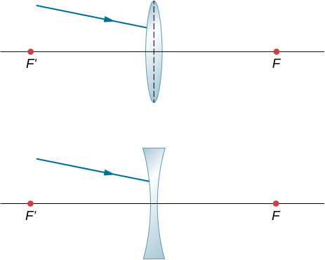
- [openstax univ. phys. vol.3 – 2.107] Trace rays to find which way the given ray will emerge after refraction through the thin lens in the following figure. Assume a thin-lens approximation. (Hint: Pick a point P on the given ray in each case. Treat that point as an object. Now, find its image Q. Use the rule: All rays on the other side of the lens will either go through Q or appear to be coming from Q.)
- [openstax univ. phys. vol. 3 – 2.108] Copy and draw rays to find the final image in the following diagram. (Hint: Find the intermediate image through lens alone. Use the intermediate image as the object for the mirror and work with the mirror alone to find the final image.)

- [openstax univ. phys. vol. 3 – 2.109] A concave mirror of radius of curvature 10 cm is placed 30 cm from a thin convex lens of focal length 15 cm. Find the location and magnification of a small bulb sitting 50 cm from the lens by using the algebraic method.
- [openstax univ. phys. vol. 3 – 2.121] Copy and draw rays to figure out the final image.


