Kinematics – Motion in Two Dimensions
Last Update: 5/14/2024
Vector addition and subtraction: a graphical method
A vector is a quantity that has magnitude and direction. Displacement, velocity, acceleration, and force, for example, are all vectors. In one-dimensional, or straight-line, motion, the direction of a vector can be given simply by a plus or minus sign. In two dimensions (2-d), however, we specify the direction of a vector relative to some reference frame (i.e., coordinate system) using an arrow having a length proportional to the vector’s magnitude and pointing in the direction of the vector.
Figure 4.1 shows such a graphical representation of a vector, using as an example the total displacement for the helicopter flying in a city. If this helicopter travels 9 blocks east and 5 blocks north, the displacement is 10.3 blocks at an angle of 29.1° north of east.

To describe the resultant vector for the helicopter flying in a city considered in Figure 4.1 graphically, draw an arrow to represent the total displacement vector D. Using a protractor, draw a line at an angle θ relative to the east-west axis. The length D of the arrow is proportional to the vector’s magnitude and is measured along the line with a ruler. In this example, the magnitude D of the vector is 10.3 units, and the direction θ is 29.1o north of east.
-
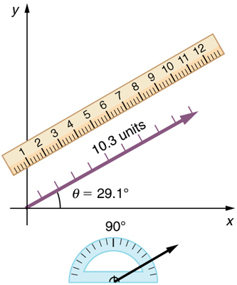
Figure 4.2

vector addition: tail to tip method
The tail-to-tip method is a graphical way to add vectors, described in Figure 4.3 below and in the steps following. The tail of the vector is the starting point of the vector, and the head (or tip) of a vector is the final, pointed end of the arrow. This method is illustrated for the two displacements of the person walking in a city considered in Figure 4.1.

Step 1. Draw an arrow to represent the first vector (9 blocks to the east) using a ruler and protractor.

Step 2. Now draw an arrow to represent the second vector (5 blocks to the north). Place the tail of the second vector at the head of the first vector.

Step 3. If there are more than two vectors, continue this process for each vector to be added. Note that in our example, we have only two vectors, so we have finished placing arrows tip to tail.
Step 4. Draw an arrow from the tail of the first vector to the head of the last vector. This is the resultant, or the sum, of the other vectors.

Step 5. To get the magnitude of the resultant, measure its length with a ruler. The length of the arrow D is measured to be 10.3 units
Step 6. To get the direction of the resultant, measure the angle it makes with the reference frame using a protractor. Its direction described as the angle with respect to the east (or horizontal axis), θ is measured with a protractor to be 29.10.
The graphical addition of vectors is limited in accuracy only by the precision with which the drawings can be made and the precision of the measuring tools.
Example 4.1- Adding Vectors Graphically Using the Tail-To-Tip Method: A Woman Takes a Walk
Use the graphical technique for adding vectors to find the total displacement of a person who walks the following three paths (displacements) on a flat field. First, she walks 25.0 m in a direction 

Strategy
Represent each displacement vector graphically with an arrow, labeling the first A, the second B, and the third C, making the lengths proportional to the distance and the directions as specified relative to an east-west line. The tail-to-tip method outlined above will give a way to determine the magnitude and direction of the resultant displacement, denoted

Solution
(1) Draw the three displacement vectors.

(2) Place the vectors tail-to-tip retaining both their initial magnitude and direction.

(3) Draw the resultant vector, R

(4) Use a ruler to measure the magnitude of R and a protractor to measure the direction of R. While the direction of the vector can be specified in many ways, the easiest way is to measure the angle between the vector and the nearest horizontal or vertical axis. Since the resultant vector is south of the eastward pointing axis, we flip the protractor upside down and measure the angle between the eastward axis and the vector.

In this case, the total displacement R is seen to have a magnitude of 50.0 m and to lie in a direction 7.0° south of east. By using its magnitude and direction, this vector can be expressed as R= 50.0m and 

Discussion
The tail-to-tip graphical method of vector addition works for any number of vectors. It is also important to note that the resultant is independent of the order in which the vectors are added. Therefore, we could add the vectors in any order as illustrated below and we will still get the same solution.

Here, we see that when the same vectors are added in a different order, the result is the same. This characteristic is true in every case and is an important characteristic of vectors. Vector addition is commutative. Vectors can be added in any order.

Vector Subtraction
Vector subtraction is a straightforward extension of vector addition. To define subtraction (say we want to subtract B from A, written A–B, we must first define what we mean by subtraction. Subtracting B from A is the same thing as adding -B to A. In other words
A–B=A+(-B)
By definition, when a vector and its negative are added together the result must be zero. This means that graphically the negative of any vector has the same magnitude but the opposite direction, as shown in Figure 4.7. In other words, vector B has the same length as vector B but points in the opposite direction. Essentially, we just flip the vector so it points in the opposite direction.

Example 4.2 – Subtracting Vectors Graphically: A Woman Sailing a Boat
A woman sailing a boat at night is following directions to a dock. The instructions read to first sail 27.5 m in a direction 


We can represent the first leg of the trip with a vector A and the second leg of the trip with a vector B. The dock is located at a location A + B. If the woman mistakenly travels in the opposite direction for the second leg of the journey, she will travel a distance B (30.0 m) in the direction 180° – 112°=68° south of east. We represent this as -B as shown below. The vector -B has the same magnitude as B but is in the opposite direction. Thus, she will end up at a location A + (-B) or A-B

We will perform vector addition to compare the location of the dock, A+B, with the location at which the woman mistakenly arrives, A+(-B)
Solution
(1) To determine the location at which the woman arrives by accident, draw vectors A, and -B.
(2) Place the vectors tail-to-tip.
(3) Draw the resultant vector R.
(4) Use a ruler and protractor to measure the magnitude and direction of vector R.

In this case, R=23.0m and Θ=7.5° south of east.
(5) To determine the location of the dock, we repeat this method to add vectors A and B. We obtain the resultant vector R’.

In this case, R=52.9m and Θ=90.1° north of east.
We can see that the woman will end up a significant distance from the dock if she travels in the opposite direction for the second leg of the trip.
Discussion
Because subtraction of a vector is the same as addition of a vector with the opposite direction, the graphical method of subtracting vectors works the same as for addition.
The following video demonstrates how to construct a scaled diagram to determine the sum of several vectors. It also discusses the common errors that might occur.
Multiplication of Vectors and Scalars
If we decided to walk three times as far on the first leg of the trip considered in the preceding example, then we would walk 3×27.5m or 82.5 m, in a direction 66.0° north of the east. This is an example of multiplying a vector by a positive scalar. Notice that the magnitude changes, but the direction stays the same.
If the scalar is negative, then multiplying a vector by it changes the vector’s magnitude and gives the new vector the opposite direction. For example, if you multiply by –2, the magnitude doubles but the direction changes. We can summarize these rules in the following way: When vector A is multiplied by a scalar c,
- the magnitude of the vector becomes the absolute value of cA
- if c is positive, the direction of the vector does not change
- if c is negative, the direction is reversed
Note that division is the inverse of multiplication. For example, dividing by 2 is the same as multiplying by the value (1/2). The rules for multiplication of vectors by scalars are the same for division; simply treat the divisor as a scalar between 0 and 1.
The following figure shows vector  along with
  ,
,  , and
, and  .
.

vector addition and subtraction: analytical method
Analytical methods of vector addition and subtraction employ geometry and simple trigonometry rather than the ruler and protractor of graphical methods. Part of the graphical technique is retained because vectors are still represented by arrows for easy visualization. However, analytical methods are more concise, accurate, and precise than graphical methods, which are limited by the accuracy with which a drawing can be made. Analytical methods are limited only by the accuracy and precision with which physical quantities are known.
Resolving a Vector into Perpendicular Components
We very often need to separate a vector into perpendicular components. For example, given a vector like A in Figure 4.8, we may wish to find which two perpendicular vectors, Ax and Ay, add to produce it.

Ax and Ay are defined to be the components of vector A along the x– and y-axes. The three vectors Ax, Ay, and A form a right triangle:

. However, it is not true that the sum of the magnitudes of the vectors is also equal. That is, |
 |
 |
 |


Unit vectors
When we express a vector in terms of its components, it is customary to use unit vectors to indicate directions. A unit vector has a magnitude of 1 unit, and it points toward a specific direction. In an xyz coordinate system, each axis has its own unit vector. The unit vector for the x-axis, y-axis, and z-axis are respectively  ,
,  , and
, and  , and they point toward the positive x, y, and z directions. For example, vector A in Figure 4.19 can be expressed in terms of unit vectors as following.

Calculating a Resultant Vector
If the perpendicular components Ax and Ay of vector A are known, then the magnitude (size) of vector A can also be found analytically. To find the magnitude of a vector from its perpendicular components, we can use the Pythagorean theorem. To determine the direction of vector A, we can calculate the angle Θ, using sinΘ, cosΘ, or tanΘ as shown in Figure 4.11.


Therefore

Adding Vectors Using Analytical Methods
To see how to add vectors using perpendicular components, consider Figure 4.12, in which the vectors A and B are added to produce the resultant vector R.

If A and B represent two legs of a walk (two displacements), then R is the total displacement. The person taking the walk ends up at the tip of R<span id=”MathJax-Element-164-Frame” class=”MathJax” style=”font-style: normal; font-weight: normal; line-height: normal; font-size: 14px; text-indent: 0px; text-align: left; text-transform: none; letter-spacing: normal; float: none; direction: ltr; max-width: none; max-height: none; min-width: 0px; min-height: 0px; border: 0px; padding: 0px; margin: 0px;” role=”presentation” data-mathml=”R.R.”>. There are many ways to arrive at the same point. In particular, the person could have walked first in the x-direction and then in the y-direction. Those paths are the x– and y-components of the resultant, Rx and Ry. If we know Rx and Ry, we can find R and Θ using the Pythagorean Theorem and trig functions. This process is outlined below.
Step 1. Identify the x- and y-axes that will be used in the problem. Then, find the components of each vector to be added along the chosen perpendicular axes. In Figure 4.13, these components are Ax, Ay, and Bx, By.

 and
and 

Components along the same axis, say the x-axis, are vectors along the same line and, thus, can be added to one another like ordinary numbers. The same is true for components along the y-axis. (For example, a 9-block eastward walk could be taken in two legs, the first 3 blocks east and the second 6 blocks east, for a total of 9, because they are along the same direction.) So resolving vectors into components along common axes makes it easier to add them. Now that the components of vector R are known, its magnitude and direction can be found.
Step 3. To get the magnitude of the resultant vector, vector R, use the Pythagorean theorem:

Step 4. To get the direction of the resultant, use trig functions to find the angle that vector R makes with the horizontal axis:


Example 4.3 – Adding Vectors Using Analytical Method
Vector A represents the first leg of a walk in which a person walks 53.0 m in a direction 20.0° north of east. Vector B represents the second leg, a displacement of 34.0m in a direction 63.0° north of east as shown in the figure below. Determine the total displacement by adding vector A to vector B.

Strategy
The components of vector A and vector B along the x– and y-axes represent walking due east and due north to get to the same ending point. Once found, they are combined to produce the resultant.
Solution
Following the method outlined above, we first find the components of vector A and vector B along the x– and y-axes.

|

|
|
|
|

|

|


 |
 |
 |
 |
 |
 |
Now we can find the magnitude of the resultant by using the Pythagorean theorem:


Finally, we determine the direction of the resultant vector R by finding Θ, the angle vector R makes with the horizontal axis.


Video Example – Finding the total displacement
Use the following simulation to practice vector addition and subtraction. You can try doing the calculations to determine the sum or the difference of two or more vectors and then check your calculations with this simulation.
Kinematics quantities as vectors
To describe motion in two and three dimensions, we must first establish a coordinate system and a convention for the axes. We generally use the coordinates x, y, and z to locate a particle at point P(x, y, z) in three dimensions. If the particle is moving, the variables x, y, and z change as time goes on. This means that x, y, and z are functions of time (t):


With our definition of the position of a particle in three-dimensional space, we can formulate the three-dimensional displacement as


In this book, we will mostly discuss one-dimensional motion (motion confined to a straight line) and two-dimensional motion (motion in a plane). In two dimensions, the displacement vector is:


The vector notations for displacement, average velocity, and average acceleration in two dimensions are:
| Displacement Vector |  |
| Average Velocity |  |
| Average Acceleration |  |
Attributions
This chapter contains material taken from “Openstax College Physics-Kinematics in Two Dimensions” , and Openstax University Physics-volume 1-Displacement and Velocity Vectors by Openstax and is used under a CC BY 4.0 license. Download these books for free at Openstax-College Physics and Openstax-University Physics
To see what was changed, refer to the List of Changes.
questions and Problems
questions
- [LibreText-College Physics 1e-Openstax]Suppose you add two vectors A and B. What relative direction between them produces the resultant with the greatest magnitude? What is the maximum magnitude? What relative direction between them produces the resultant with the smallest magnitude? What is the minimum magnitude?
- [LibreText-College Physics 1e-Openstax]Give an example of a nonzero vector that has a component of zero.
- [LibreText-College Physics 1e-Openstax]Explain why a vector can not have a component greater than its own magnitude.
- [LibreText-College Physics 1e-Openstax]If vectors A and B are perpendicular, what is the component of vector A along the direction of vector B? What is the component of vector B along the direction of vector A?
problems
- [openstax univ. phys. vol. 1 – 2.37-modified] Assuming the +x-axis is horizontal and points to the right, find the components of the following vectors and express each vector using unit vector notation.
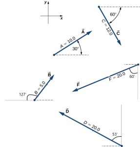
fig-prob4.1 [Image Description] - [openstax unv. phys. vol. 1 – 2.28(edited)] For the vectors given in the previous problem, find the following.
-
- A small plane flies 40.0km in a direction 60º north of east and then flies 30.0km in a direction 15º west of north. Determine the magnitude and direction of the total displacement vector?
- Suppose you walk 12.0m in a direction 20.0° west of north and then 30.0m in a direction 40.0° south of west. What is your total displacement?
- [LibreText-College Physics 1e-Openstax] A new landowner has a triangular piece of flat land she wishes to fence. Starting at the west corner, she measures the first side to be 80.0m long and the next to be 105m. These sides are represented as displacement vectors A and B in the figure. She then correctly calculates the length and orientation of the third side, C. What is her result?
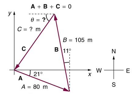
fig-prob4.5 [Image Description] - [LibreText-College Physics 1e-Openstax] A farmer wants to fence off his four-sided plot of flat land. He measures the first three sides, shown as vectors A, B, and C in the figure below, and then correctly calculates the length and orientation of the fourth side D. What is his result?
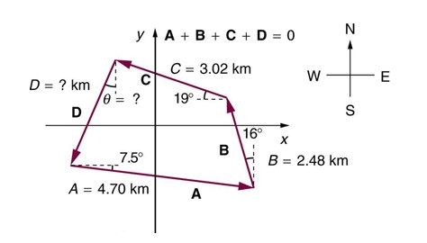
fig-prob4.6 [Image Description]


image Descriptions
fig-prob4.1 image description – The image shows five separate vectors. Vector A is 10.0 units and makes a 30º angle from the positive x-axis in counter clockwise direction. Vector B is 5.0 units and makes a 127º angle from the negative x-axis in clockwise direction. Vector C is 12.0 units and makes a 60º angle from the positive x-axis in clockwise direction. Vector D is 20.0 units and makes a 53º angle from the positive y-axis in counter clockwise direction. Vector F is 20.0 units and makes a 60º angle from the negative y-axis in clockwise direction. [Return to the image]
fig-prob4.5 image description – The image shows three vectors on an x-y coordinate system forming a triangle. The cardinal directions are shown with west-east along the x-axis and north-south along the y-axis. Vector A has a magnitude of 80m and is 21º below the x-axis. Vector B starts at the tip of vector A. It has a magnitude of 105m, and makes an 11º angle to the left of a vertical dashed line. Vector C starts at the tip of vector B and ends on the tail of vector A, completing the triangle. The magnitude of vector C, and the angle vector C makes below the horizontal are unknown. It is stated that vector A, plus vector B, plus vector C equals zero. [Return to the image]
fig-prob.4.6 image description – The image shows four vectors on an x-y coordinate system forming a quadrilateral. The cardinal directions are shown with west-east along the x-axis and north-south along the y-axis. Vector A has a magnitude of 4.70 km and is 7.5º below the x-axis. Vector B starts at the tip of vector A. It has a magnitude of 2.48 km, and makes an 16º angle to the left of a vertical dashed line. Vector C starts at the tip of vector B. It has a magnitude of 3.02 km, and makes a 19º angle above the horizontal line, pointing to the left. Vector D starts at the tip of vector C and ends on the tail of vector A, completing the quadrilateral. The magnitude of vector D, and the angle vector D makes with a vertical dashed line are unknown. It is stated that vector A, plus vector B, plus vector C, plus vector D equals zero. [Return to the image]
