Rotational Motion
Last Update: 12/06/2022
kinematics of rotational motion
As we saw in UNIT 14, to describe rotational motion it is more convenient to use the rotation angle and angular velocity. If the rotating object speeds up or slows down, we use angular acceleration to indicate how fast the angular velocity changes. In other words, angular acceleration is the rate of change of angular velocity. Therefore, the average angular acceleration,  , is defined as
 Average Angular Acceleration
Angular acceleration is measured in rad/s2. Since the tangential (linear) velocity, vt, of a point on a rotating object and the angular velocity are related as vt =rω, we can rewrite the above equation as

As we saw in our discussion of non-uniform circular motion (UNIT 9)  . This results in

Similar relationship exists between the instantaneous tangential acceleration and the instantaneous angular acceleration. Table 15.1 shows the relationship between the magnitudes of all rotational and tangential (linear) variables for circular motion.
| Rotational | Translational | Relationship (r=radius) |
 |
 |
 |
 |
 |
 |
 |
 (due to speeding up/slowing down) (due to speeding up/slowing down) |
 |
 (due to change in direction of velocity) (due to change in direction of velocity) |
 |
Now let’s consider rotational motion with constant angular acceleration. The kinematics equations for this type of motion are identical to the equations we had for linear motion with constant acceleration, with the only difference that the linear quantities of position, velocity, and acceleration are replaced with their counterpart for rotational motion, namely rotation angle, angular velocity, and angular acceleration.
Translational Motion with Constant Acceleration |
Rotational Motion with Constant Angular Acceleration |
 |
 |
 |
 |
 |
 |
 |
 |
Keep in mind that angular velocity and angular acceleration are both vectors. These vectors are in the same direction when the object is speeding up and they are in the opposite directions when the object is slowing down. As mentioned in UNIT 14, when rotation is in a counterclockwise direction, angular velocity is positive, and when rotation is in a clockwise direction, angular velocity is negative.
Example 15.1
A deep-sea fisherman hooks a big fish that swims away from the boat pulling the fishing line from his fishing reel. The whole system is initially at rest and the fishing line unwinds from the reel at a radius of 4.50 cm from its axis of rotation. The reel is given an angular acceleration of 110rad/s2 for 2.00 s (Figure 15.1).

a) What is the final angular velocity of the reel?
b) At what speed is the fishing line leaving the reel after 3.00 s elapses?
c) How many revolutions does the reel make?
d) How many meters of the fishing line comes off the reel during this time?
e) Now let us consider what happens if the fisherman applies a brake to the spinning reel, achieving an angular acceleration of -300rad/s2. How long does it take the reel to come to a stop?
Solution for (a)
Since we know the angular acceleration, the initial angular velocity, and the time interval during which the reel accelerates, we can use


Solution for (b)
We use the relationship between linear speed (tangential speed) and angular speed.


Solution for (c)
We need to find the change in the rotational angle, ΔΘ, in radian, and then convert that to number of revolution, using the fact that 1rev=2π rad.


Solution for (d)
The length of the arc subtended by the rotational angle is the linear distance, which in this case is the length of the fishing line. From Table 15.1


Solution for (e)


Video Example – Spining top slowind down
dynamics of rotational motion
torque
We have defined angular acceleration, , as the rate of change of angular velocity.

In this unit, we discuss the cause of this angular acceleration.
Generally speaking, to cause any change in the rotational motion, such as speeding up or slowing down, the rotating object must interact with something external. We know interaction between objects results in force between them. But not all forces are capable of changing the angular velocity of a rotating object and make it speed up or slow down. Consider the wrench and bolt depicted in Figure 15.2.

The force applied in Figure 15.2 (a) does not cause rotation, but if the same force is applied at a different angle as shown in Figure 15.2 (b), the wrench will rotate and there is a change in its angular velocity. If a force can cause rotation, we say the force produces a torque. In other words, torque is the turning effect of a force. What determines the size and direction of a torque depends on the size of the force, where the force is applied on the object, and the direction of the force. For example, a force applied perpendicular to the wrench and at the end of it produces a greater torque than the same force, with the same direction applied closer to the bolt. Similarly, a force applied at the end of the wrench and perpendicular to it produces a greater torque than an equal force applied to the same point but at an angle other than 90°.
Another familiar example is how we rotate a door to open it. In Figure 15.3. (a) a force F acting at a distance r from the hinges (the pivot point) produces a counterclockwise torque. In (b) A smaller counterclockwise torque is produced when a smaller force acts at the same distance r from the hinges. In (c) the same force as in (a) produces a smaller counterclockwise torque when applied at a smaller distance from the hinges. In (d) A smaller counterclockwise torque is produced by the same magnitude force as (a) acting at the same distance as (a) but at an angle that is less than 90°.

In general, the magnitude of torque is given by
 Torque
Where is the magnitude of the force creating the torque, r is the distance between the axis of rotation and where the force is applied, and Θ is the angle between r and F.
Torque is a vector quantity and its direction is found by using the right-hand rule. To use the right-hand rule, put your right hand in the direction of r, pointing from the axis of rotation to where the force is applied, then close your hand in the direction of the force. Your right thumb is then in the direction of the torque. If the rotation is in the x-y plane, a torque in the positive z direction is counterclockwise and a torque in the negative z direction is clockwise. Right-hand rule is demonstrated in Figure 15.4.

Units of torque in the SI system is mN. This is the same combination of units we called Joules for work and energy. But torque is a completely different quantity and we leave its units as mN.
Mechanical Advantage
Simple machines are devices that can be used to multiply or augment a force that we apply – often at the expense of a distance through which we apply the force. The word for “machine” comes from the Greek word meaning “to help make things easier.” Levers, gears, pulleys, wedges, and screws are some examples of machines. Energy is still conserved for these devices because a machine cannot do more work than the energy put into it. However, machines can reduce the input force that is needed to perform the job. The ratio of output to input force magnitudes for any simple machine is called its mechanical advantage (MA).

One of the simplest machines is the lever, which is a rigid bar pivoted at a fixed place called the fulcrum. Torques are involved in levers, since there is rotation about a pivot point. Distances from the physical pivot of the lever are crucial, and we can obtain a useful expression for the MA in terms of these distances. For example, a nail puller is a lever.

Crowbars, seesaws, and other such levers are all analogous to a nail puller. In the diagrma above, Fi is the input force. The output force is the force that the nail puller applies to the nail (not shown above) which is, according to Newton’s Third Law equal in magnitude to Fn, the force that the nail applies on the nail puller. The torques due to Fi and Fn must be equal to each other if the nail is not moving. In order for the nail to actually move, the torque due toFi must be ever-so-slightly greater than torque due to Fn. Hence, at equilibrium

Since Fi is the input force, and FN is the output force, the mechanical advantage of the nail puller is


Example 15.2 – Calculating Torque on a Rigid Body
Figure 15.5 shows several forces acting at different locations and angles on a flywheel. We have  , and
, and  and r=0.50m. Find the net torque on the flywheel about an axis through the center.

Solution
The net torque is the sum of all torques acting on the flywheel. We calculate the magnitude of each torque using  . Torques that are clockwise will be recorded as negative, and torques that are counterclockwise will be positive.


Discussion
Notice that since the line of action of  goes through the pivot point (where the axis of rotation meets the object), this force does not produce a torque. If the flywheel was not mounted on a fixed axis, would cause the center of mass to accelerate.
Video Example – Torque on a wire spool
Newton’s Second law for rotational motion
Just like an unbalanced force causes linear acceleration, an unbalanced torque (a net torque) results in angular acceleration. Newton’s Second Law for rotational motion is very similar to the one for linear motion and is expressed as
 Newton’s Second Law for rotational motion
Where  is moment of inertia.
This means that how fast an object’s rotation speeds up or slows down is directly proportional to the net torque acting on it and is inversely proportional to its resistance against change in rotation, which is its moment of inertia.
Conditions for equilibrium
An object is in equilibrium if it doesn’t have any linear or angular acceleration. Therefore, based on Newton’s Second Law, the two conditions for equilibrium are:


Example 15.3 –Calculating the Effect of Mass Distribution on a Merry-Go-Round
Consider the father pushing a playground merry-go-round in Figure 15.6. He exerts a force of 250 N at the edge of the 50.0-kg merry-go-round, which has a 1.50-m radius. Consider the merry-go-round itself to be a uniform disk with negligible friction. Calculate the angular acceleration produced
(a) when no one is on the merry-go-round and
(b) when an 18.0-kg child sits 1.25 m away from the center.

Solution for (a)
To find the angular acceleration we need to use Newton’s Second Law for rotational motion. Since friction on the merry-go-round is negligible, the only force producing torque is the force applied by the person. Let’s calculate the torque due to this force.


Now let’s find the moment of inertia of the merry-go-round. Treating the merry-go-round as a uniform disk, we look up the formula for moment of inertia in Table 14.1


Using Newton’s Second Law for rotation we can solve for the angular acceleration.


Solution for (b)
The net torque is still the same as (a), but the moment of inertia is sum of the moment of inertia of the merry-go-round and the moment of inertia of the child rotating about an axis that goes through the center of the merry-go-round. We can treat the child as a point object rotating about a fixed axis, with a moment of inertia given by  .
.


Now, find the angular acceleration using Newton’s Second Law for rotation.


Discussion
The angular acceleration is less when the child is on the merry-go-round than when the merry-go-round is empty, as expected. The angular accelerations found are quite large, partly due to the fact that friction was considered to be negligible. If, for example, the father kept pushing perpendicularly for 2.00 s, he would give the merry-go-round an angular velocity of 13.3 rad/s when it is empty but only 8.89 rad/s when the child is on it. In terms of revolutions per second, these angular velocities are 2.12 rev/s and 1.41 rev/s, respectively. The father would end up running at about 50 km/h in the first case.
Video Example – Falling block rotating a pulley
Torques in the Human Body
Muscles, bones, and joints are some of the most interesting applications of torques. There are some surprises. Muscles, for example, exert far greater forces than we might think.

Muscles can only contract, so they occur in pairs. In the arm, the biceps muscle is a flexor—that is, it closes the limb. The triceps muscle is an extensor that opens the limb. This configuration is typical of skeletal muscles, bones, and joints in humans and other vertebrates. Most skeletal muscles exert much larger forces within the body than the limbs apply to the outside world. The reason is clear once we realize that most muscles are attached to bones via tendons close to joints, causing these systems to have mechanical advantages much less than one. Viewing them as simple machines, the input force is much greater than the output force, as seen in Example 15.4. Training coaches and physical therapists use the knowledge of relationships between forces and torques in the treatment of muscles and joints.
The back is considerably more complicated than the arm or leg, with various muscles and joints between vertebrae, all having mechanical advantages less than 1. Back muscles must, therefore, exert very large forces, which are borne by the spinal column. Discs crushed by mere exertion are very common. The jaw is somewhat exceptional—the masseter muscles that close the jaw have a mechanical advantage greater than 1 for the back teeth, allowing us to exert very large forces with them. A cause of stress headaches is persistent clenching of teeth where the sustained large force translates into fatigue in muscles around the skull.
The figure below shows how bad posture causes back strain. In part (a), we see a person with good posture. Note that her upper body’s cg is directly above the pivot point in the hips, which in turn is directly above the base of support at her feet. Because of this, her upper body’s weight exerts no torque about the hips. The only force needed is a vertical force at the hips equal to the weight supported. No muscle action is required, since the bones are rigid and transmit this force from the floor. This is a position of unstable equilibrium, but only small forces are needed to bring the upper body back to vertical if it is slightly displaced. Bad posture is shown in part (b); we see that the upper body’s cg is in front of the pivot in the hips. This creates a clockwise torque around the hips that is counteracted by muscles in the lower back. These muscles must exert large forces, since they have typically small mechanical advantages.

Example 15.4 – Forces applied by bones and muscles
The figure below shows the forearm of a person holding a book. The biceps exert a force FB to support the weight of the forearm and the book. The triceps is assumed to be relaxed. In (b), you can view an approximately equivalent mechanical system with the pivot at the elbow joint.
 |
 |
a) Calculate the force the biceps muscle must exert to hold the forearm and its load as shown in (a).
b) Calculate the downward force FE exerted by the humerus bone in Figure 15.7 at the elbow joint.
Solution for (a)
There are four forces acting on the forearm and its load (the system of interest). The magnitude of the force of the biceps is FB; that of the elbow joint is FE; that of the weights of the forearm is wa, and its load is wb. Two of these are unknown (FB and FE), so that the first condition for equilibrium () cannot by itself yield FB. But if we use the second condition () and choose the pivot to be at the elbow, then the torque due to FE is zero, and the only unknown becomes FB.
The torques created by the weights are clockwise relative to the pivot, while the torque created by the biceps is counterclockwise. Also, note that sinθ=1 for all forces, since θ=90° for all forces. Thus, the second condition for equilibrium becomes:


Solution for (b)
Now that we know FB we can use the first condition for equilibrium to solve for FE.


 (rounding to 2 sig figs)
Discussion
The combined weight of the arm and its load is  , so that the ratio of the force exerted by the biceps to the total weight is

This means that the biceps muscle is exerting a force 7.4 times the weight supported!!
In the above example of the biceps muscle, the angle between the forearm and upper arm is 90°. If this angle changes, the force exerted by the biceps muscle also changes. In addition, the length of the biceps muscle changes. The force the biceps muscle can exert depends upon its length; the force is smaller when the muscle is shorter than when it is stretched.
The downward force applied to the elbow joint is also very large. In this example the this force is 6.4 times larger than the supported weight, as shown below.

Because muscles can contract, but not expand beyond their resting length, joints and muscles often exert forces that act in opposite directions and thus subtract.
Investigate the conditions for equilibrium with the following simulation. Use the Blance Lab and see if you can figure out the mass of the mystery boxes.
Angular Momentum
In UNIT 12 we defined linear momentum as the product of mass and velocity.
 Linear Momentum
Similarly, we can define angular momentum of a rigid object rotating about a fixed axis as the product of moment of inertia and angular velocity.
 Angular Momentum
In UNIT 12 we also saw that an alternative way to express Newton’t Second Law for linear motion is in terms of momentum. More specifically, we showed that
 is the same as
Similar reasoning can be used for rotational motion. In other words
 is the same as
From  we see that if
  then
then  . This means that when the net torque on a system is zero, the angular momentum of the system does not change. This is known as conservation of angular momentum.
Example 15.5 – Ice Skater
Suppose an ice skater, such as the one in Figure 15.8, is spinning at 0.800 rev/s with her arms extended. She has a moment of inertia of 2.34 kgm2 with her arms extended and of 0.363 kgm2 with her arms close to her body.
(a) What is her angular velocity in revolutions per second after she pulls in her arms?
(b) What is her rotational kinetic energy before and after she does this?

Solution for (a)
There is no external torque acting on the ice skater as she pulls her arms in. Therefore, her angular momentum is conserved.


Solution for (b)
To determine rotational kinetic energy, we must convert units of angular speed to rad/s.


Now we can calculate the kinetic energy.


Discussion
In both parts, there is an impressive increase. Most world-class skaters can achieve spin rates about this great. The final kinetic energy is much greater than the initial kinetic energy. The increase in rotational kinetic energy comes from work done by the skater in pulling in her arms. This work is internal work that depletes some of the skater’s food energy.
Video Example – Bug moving on a rotating disk
Attributions
This chapter contains material taken from Openstax College Physics-Rotational Motion and Angular Momentum, and Openstax University Physics Volume 1 – Fixed Axis Rotation and is used under a CC BY 4.0 license. Download these books for free at Openstax
To see what was changed, refer to the List of Changes.
Example 15.4 is adopted from Openstaxcollege and used under a CCBY 4.0 License.
problems
- [openstax univ. phys. vol. 1 – 10.39] The angular velocity of a rotating rigid body increases from 500rev/min to 1500 rev/min in 120 s.
- What is the angular acceleration of the body?
- Through what angle does it turn in this 120s?
- [openstax univ. phys. vol. 1 – 10.41] A wheel, 1.00 m in radius, has an initial angular velocity is 2.00 rad/s and angular acceleration of 4.00rad/s2.
- What is its angular velocity after 10.0 s?
- Through what angle does it rotate in the 10.0-s interval?
- What are the tangential speed and acceleration of a point on the rim of the wheel at the end of the 10.0-s interval?
- A point at the edge of a circular disk of radius 10.0 cm has an initial linear speed of 0.200m/s when the disk starts to slow down at a constant rate and eventually stops in 5.00s.
- Determine the disk’s angular acceleration.
- How many times does the disk rotate before it stops?
- How long does it take for the disk to reach an angular speed of 0.500rad/s?
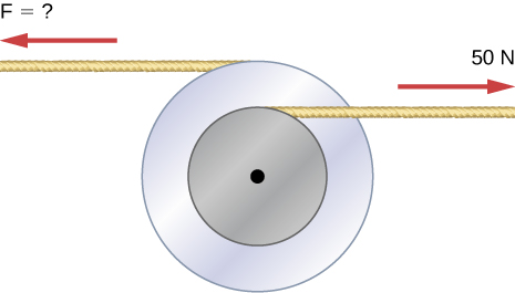
- [openstax univ. phys. vol. 1 – 10.71] Two flywheels of negligible mass and different radii are bonded together and rotate about a common axis (see below). The smaller flywheel with a radius of 30.0 cm has a cord that has a pulling force of 50.0 N on it. What pulling force needs to be applied to the cord connecting the larger flywheel of a radius of 50.0 cm such that the combination does not rotate?
- [openstax univ. phys. vol. 1 – 10.86] A flywheel with a moment of inertia of 50.0kgm2 starts from rest and acquires an angular velocity of 200 rad/s while subject to a constant torque from a motor for 5.00s.
- What is the angular acceleration of the flywheel?
- What is the magnitude of the torque?
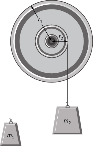
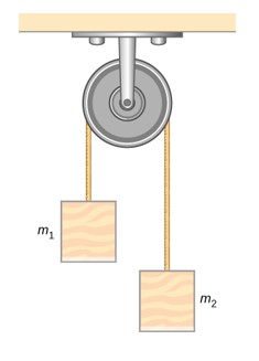
- [openstax univ. phys. vol. 1 – 10.92] A pulley with a moment of inertia of 2.00kgm2 is mounted on a wall as shown in the following figure. Light strings are wrapped around two circumferences of the pulley and weights are attached. r1=50.0cm, r2=20.0cm, m1=1.00kg, m2=2.00kg
- What is the angular acceleration of the pulley?
- What is the linear acceleration of the weights? Assume the following data:
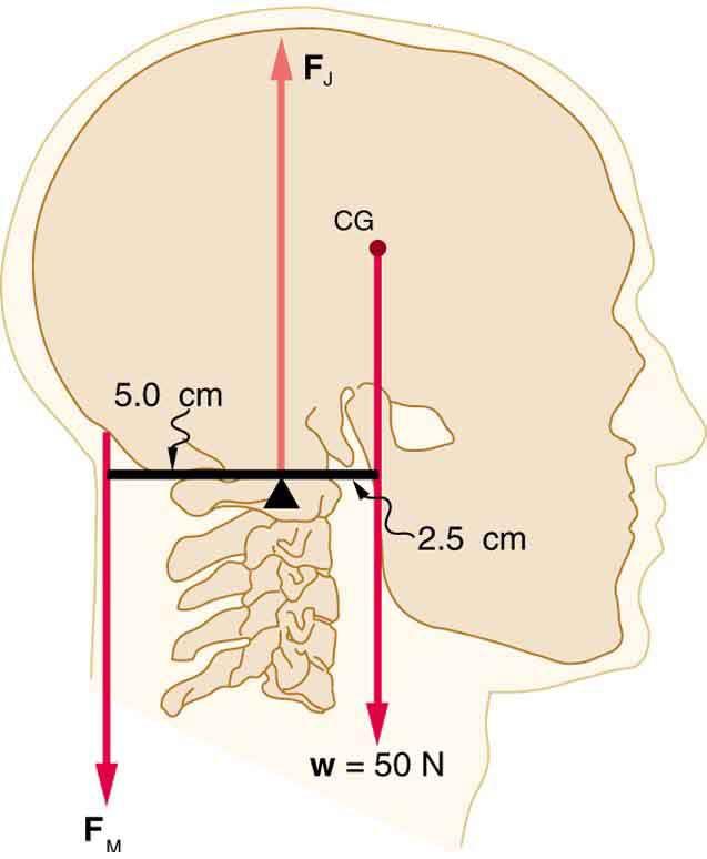
- [openstax college physics – 9.32] Even when the head is held erect, as shown below, its center of mass is not directly over the principal point of support (the atlanto-occipital joint). The muscles at the back of the neck should therefore exert a force to keep the head erect. That is why your head falls forward when you fall asleep in class.
- Calculate the force exerted by these muscles using the information in the figure. Use 3 significant figures for all the values.
- What is the force exerted by the pivot on the head?
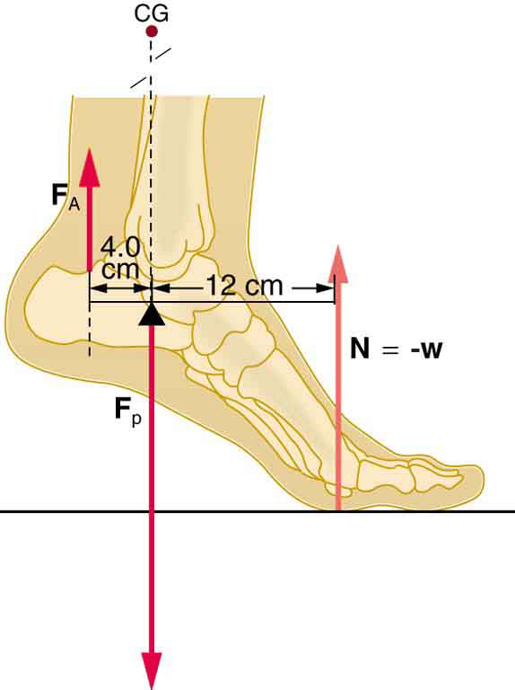
- [openstax college physics. 9.33] A 75.0-kg man stands on his toes by exerting an upward force through the Achilles tendon, as shown below. Use 3 significant figures for all the values. Notice that since the man’s weight is on the ball of his foot and he is at equilibrium, the normal force applied by the ground on the ball of the foot balances the gravitational force.
- What is the force in the Achilles tendon if he stands on one foot?
- Calculate the force at the pivot of the simplified lever system shown—that force is representative of forces in the ankle joint.
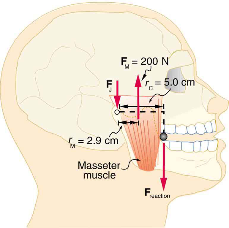
- [openstax college physics. 9.35] Unlike most of the other muscles in our bodies, the masseter muscle in the jaw, as illustrated below, is attached relatively far from the joint, enabling large forces to be exerted by the back teeth.
- Using the information in the figure(use 3 significant figures for all values), calculate the force exerted by the lower teeth on the bullet.
- Calculate the force on the joint.
- In the setup shown below the pulley is in the shape of a solid cylinder and has a mass of 0.200kg and a radius of 0.150m, m1=0.400kg, and m2=0.800kg. The pulley experiences a constant torque of 0.350mN due to the friction between the rotating pulley and its axle. Determine the magnitude of the acceleration of the two masses.
- [openstax univ. phys. vol. 1 – 11.52] A disk of mass 2.00 kg and radius 60.0 cm with a small mass of 0.0500 kg stuck at the edge is rotating at 2.00 rev/s. The small mass suddenly separates from the disk. What is the disk’s final angular speed?
- [openstax univ. phys. vol. 1 – 11.59] A bug of mass 0.0200 kg is at rest on the edge of a solid cylindrical disk (M=0.100kg, R=0.100m) rotating in a horizontal plane around the vertical axis through its center. The disk is rotating at 10.0 rad/s. The bug crawls to the center of the disk.
- What is the new angular velocity of the disk?
- What is the change in the kinetic energy of the system?
- If the bug crawls back to the outer edge of the disk, what is the angular velocity of the disk then?
- What is the new kinetic energy of the system?
- What is the cause of the increase and decrease of kinetic energy?
- [openstax univ. phys. vol. 1 – 11.63] Three children are riding on the edge of a merry-go-round that is in the shape of a solid cylinder and has a mass of 100 kg, and a radius of 1.60-m. The merry-go-round is spinning at 20.0 rpm. The children have masses of 22.0kg, 28.0kg, and 33.0kg. If the child who has a mass of 28.0kg moves to the center of the merry-go-round, what is the new angular velocity in rpm?
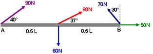
- A uniform rod has a moment of inertia of 20.0kgm2 and can rotate about point A. The length of the rod is L=1.00m.


-
- Find the net torque about point A.
- If the rod starts from rest, how long does it take to reach an angular speed of 10.0rad/s?
