Electrostatics II – Electric Potential, and Capacitors
Last Update: 06/29/2022
capacitors
A capacitor is a device used to store electric charge. Capacitors are a common element in almost all electronic devices. A system composed of two identical, parallel conducting plates separated by a distance, as in Figure 23.1, is called a parallel plate capacitor. Figure 23.2 shows what real capacitors look like.
 |
 |
When the plates are connected to the terminals of a battery, one plate becomes positively charged, and the other one negatively charged. The oppositely charged plates establish a uniform electric field between them as shown in Figure 23.1. The strength of this electric field is directly proportional to the charge stored on the plates. Since the electric field is constant, the voltage across the plates is

Where d is the distance between the plates.
Since the electric field is proportional to the charge stored on the plates, and the voltage across the plates is proportional to the electric field, it is easy to see that the voltage across the plates must be directly proportional to the charge on the plates. This relationship is written as
 Charge On A Capacitor
Where
 is the charge stored on the plates
 is the capacitance of the capacitor
 is the voltage across the plates
Capacitance is a property of the capacitor that indicates its ability to store charge. Capacitance is measured in C/V. This combination of units is known as Farad(F). The capacitance of a parallel plate capacitor with air between the plates is given by
 Capacitance Of Air-Filled Parallel Plate Capacitor
In this equation
 is a constant called the permittivity of free space and is
 is the area of one plate in m2
 is the separation distance between the two plates in m.
Example 23.1
A parallel plate capacitor has metal plates, each with an area of 25.0cm2, separated by 1.00 mm.
a) Find the capacitance of this capacitor.
b) What charge is stored in this capacitor if a voltage of 15.0V is applied to it?
Solution to a
The capacitance of a parallel plate capacitor is given by

The area has to be in m2.

Now we can calculate the capacitance


Solution to b
We can calculate the charge by using


Capacitance determines how much charge can be stored in a capacitor for a given voltage. For a parallel plate capacitor, the separation between the plates, d, plays a role. The smaller the separation distance, the higher is the capacitance. But reducing the separation distance will also increase the electric field,  . If the electric field gets too strong, the air between the plates becomes ionized and the capacitor breaks down. One way to prevent the electric field from becoming too large is to insert a good insulator, called a dielectric, between the plates. The electric field due to the charges on the plates polarizes the molecules of the dielectric, as shown in Figure 23.3.

This creates an electric field inside the dielectric in the opposite direction to the electric field of the capacitor. As a result, the net electric field becomes weaker. This will allow for more charges to be stored on the capacitor. In other words the capacitance of the capacitor increases. With a dielectric filling the space between the plates of a parallel plate capacitor, the capacitance is

Where  is the dielectric constant.
Table 23.1 lists the dielectric constant of some common dielectrics

Example23.2
An air-filled capacitor is made from two flat parallel plates 1.0 mm apart. The inside area of each plate is 8.0cm2.
(a) What is the capacitance of this set of plates?
(b) If the region between the plates is filled with mica, what is the new capacitance?
Solution for a
The capacitance of an air-filled parallel plate capacitor is given by
The area has to be in m2.


Solution for b
By inserting a dielectric between the plates the capacitance increases by a factor equal to the dielectric constant. According to Table 23.1, the dielectric constant of mica is 6.0.


energy in a charged capacitor
As we saw in UNIT 22, when a charge, q, goes through a potential difference, ΔV, its potential energy changes by  . Since the voltage across an uncharged capacitor is initially zero, no work is done and no potential energy is stored to move the very first charge on the plates. However, as the plates accumulate more charge, the voltage builds up, and more and more energy is stored in the system. At the end, when the voltage across the plates is ΔV, the work needed to put the last charge, q, on the plates is qΔV. This means that the work needed to charge the capacitor increases from 0 to qΔV while the capacitor is charging. Therefore, the overall energy stored in a charged capacitor is the average of the two. In other words

We can also use to express energy in terms of Q and C, or in terms of C and V, as indicated below
 Energy Stored In A Charged Capacitor
Example 23.3
A heart defibrillator delivers 4.00 x 10²J of energy by discharging a capacitor initially at 1.00×10⁴ V. What is its capacitance?
Solution
We can determine the capacitance by using


Difibrillator
In the event that the electrical activity of the heart is severely disrupted, cessation of electrical activity or fibrillation may occur. In fibrillation, the heartbeats in a wild, uncontrolled manner, which prevents it from being able to pump effectively. Atrial fibrillation is a serious condition, but as long as the ventricles continue to pump blood, the patient’s life may not be in immediate danger. Ventricular fibrillation is a medical emergency that requires life support, because the ventricles are not effectively pumping blood. In a hospital setting, it is often described as “code blue.” If untreated for as little as a few minutes, ventricular fibrillation may lead to brain death. The most common treatment is defibrillation, which uses special paddles to apply a charge to the heart from an external electrical source in an attempt to establish a normal sinus rhythm. A defibrillator effectively stops the heart so that the SA node can trigger a normal conduction cycle. A defibrillator is a capacitor. The video below demonstrates how it functions
capacitors in parallel and series
Several capacitors may be connected together in a variety of applications. Multiple connections of capacitors act as a single equivalent capacitor. The total capacitance of this equivalent single capacitor depends both on the individual capacitors and how they are connected. There are two simple and common types of connections, called series and parallel, for which we can easily calculate the equivalent capacitance. Certain more complicated connections can also be related to combinations of series and parallel.
Capacitance in Series
Figure 23.4 shows a series connection of three capacitors with a voltage applied.

As demonstrated in 23.4, when capacitors are connected in series, an equal amount of charge is stored on the capacitors, regardless of their capacitance. In order to understand why capacitors in series have equal charge, we need to examine how charging takes place.
The battery establishes a flow of electrons from its negative to the positive terminal. Consider the first electron reaching the bottom plate of capacitor C3 in Fig23.4. Since there is a gap or a dielectric between the plates of C3, the electron gets stuck on that plate. This excess negative charge on the bottom plate of C3 forces one electron out of the top plate, leaving the top plate positively charged. The electron that left the top plate of C3 reaches the bottom plate of C2, gets stuck, and pushes one electron out of the top plate of C2. This process continues till all the capacitors are charged. So for each electron stuck on C3, one electron leaves C3 and gets stuck on C2, and one electron leaves C2 and gets stuck on C1. That’s why all the capacitors in series end up with an equal amount of charge.
Now, let’s find the equivalent capacitance of these three capacitors in series. In other words, we are trying to find the capacitance of a single capacitor that could replace all three. This equivalent capacitor is shown in Figure 23.5.

Since the equivalent capacitor has the same effect as the three capacitors in series, it must accumulate the same charge. Therefore

To find the relationship between the voltages, remember that voltage is like the difference in elevation. The positive terminal of the battery is at the highest potential or highest elevation, and the negative terminal is at the lowest potential or elevation. As we go from the positive to the negative terminal, we have to take steps down as we go across the capacitors. This is all demonstrated in Figure 23.6.

Referring to Figure 23.6, we see that

For each capacitor, the relationship between voltage, charge, and capacitance is , or  . Keeping in mind that all charges are equal, we can rewrite the equation above as

Dividing both sides by Q yields

This result can be generalized for any number of capacitors in series.
 Capacitors In Series
Example 23.4
Three capacitors, C1=1.00μF, C1=5.00μF, C1=8.00μF are connected in series to a 12.0V battery.
a) Find the equivalent capacitance of the circuit.
b) Determine the charge and voltage for each capacitor.
Solution for (a)
We can find the equivalent capacitance for capacitors in series, using


Solution for (b)
All three capacitors and the equivalent capacitor have the same charge. Let’s find the charge on the equivalent capacitor.
 |
 |
In Figure 23.8:


So the charge on each capacitor is  . Using the capacitance and charge we can find the voltage across each capacitor.

|

|

|


Notice that  as expected.
capacitors in parallel
Figure 23.9 shows a parallel connection of three capacitors with a voltage applied. We first note that the voltage across each capacitor is the same as the voltage across the battery. This is the case because the plates of each capacitor are directly connected to the positive and negative terminals of the battery.

Therefore

Once again, we are interested in finding the equivalent capacitor- a single capacitor that could replace the three capacitors connected in parallel, as shown in Figure 23.10.

The total charge stored in the three capacitors is the sum of the charges on each capacitor. The equivalent capacitor must have the same total charge.

Using for each capacitor, including the equivalent capacitor, we can rewrite the equation above as

Divide both sides by

Once again we can generalize this to any number of capacitors.
 Capacitors In Parallel
Example 23.5
Three capacitors, C1=1.00μF, C1=5.00μF, C1=8.00μF are connected in parallel to a 12.0V battery.
a) Find the equivalent capacitance of the circuit.
b) Determine the charge and voltage for each capacitor.
Solution for (a)
The equivalent capacitance of capacitors in parallel is


Solution for (b)
The voltage across each capacitor is equal to the voltage across the battery

 |
|
Now we can find the charge on each capacitor
|
|
|
|


To check our results, we can find the charge on the equivalent capacitor and compare it with the sum of the charges on the individual capacitors.


Notice that  as expected
Attribution
This chapter contains material taken from Openstax College Physics -Electric Potential and Electric Field, and is used under a CC BY 4.0 license. Download these books for free at Openstax
The section on Defibrillator is taken from Anatomy and Physiology-Openstax. This book can be accessed for free at https://openstax.org/books/anatomy-and-physiology/pages/1-introduction
To see what was changed, refer to the List of Changes.
Problems
- [openstax univ. phys. vol.2 – 8.26] A 60.0-pF capacitor has a plate area of 0.0100m2 and vacuum between the plates. What is the separation between its plates?
- [openstax univ. phys. vol. 2 – 8.25] The plates of a parallel-plate capacitor of capacitance 5.00pF are 2.00 mm apart. What is the area of each plate?
- [openstax univ. phys. vol. 2 – 8.51] An air-filled capacitor is made from two flat parallel plates 1.00 mm apart. The inside area of each plate is 8.00cm2.
- What is the capacitance of this set of plates?
- If the region between the plates is filled with a material whose dielectric constant is 6.00, what is the new capacitance?
- [openstax univ. phys. vol. 2 – 8.31] A 4.00-pF is connected in series with an 8.00-pF capacitor and a 400-V potential difference is applied across the pair. Determine the charge and voltage for each capacitor.
- [openstax univ. phys. vol. 2 – 8.32] Three capacitors, with capacitances of C1=2.00μF, C2=3.00μF, and C3=6.00μF, respectively, are connected in parallel. A 500-V potential difference is applied across the combination. Determine the voltage across each capacitor and the charge on each capacitor.
- [openstax univ. phys. vol. 2 – 8.33(modified)] Consider the network of capacitors shown. The voltage from A to B is 10.0V. Assume three significant figures for all given quantities.
- Find the equivalent capacitance.
- Find the charge and voltage for each capacitor.

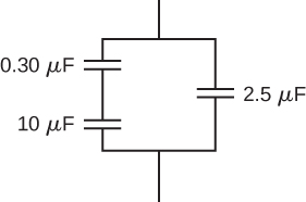
- [openstax univ. phys. vol.2 – 8.36 (modified)] The voltage across the network of capacitors shown is 12.0V. Assume three significant figures for all the given quantities.
- Find the equivalent capacitance of this network.
- Find the charge and voltage for each capacitor.
- [openstax univ. phys. vol. 2 – 8.37(modified)]The voltage across the network of capacitors shown is 9.00V. Assume three significant figures for all the given quantities.
- Find the equivalent capacitance.
- Find the charge and voltage for each capacitor.

- [openstax univ. phys. vol. 2 – 8.41] A capacitor has a charge of2.50μC when connected to a 6.00-V battery. How much energy is stored in this capacitor?
- [openstax univ. phys. vol. 2 – 8.43] A 10.0 μF capacitor of a heart defibrillator charged to 9.00×10³V?
- Determine the energy stored in this capacitor.
- How much charge is stored in this capacitor?
- [openstax univ. phys. vol. 2 – 8.48]A parallel-plate capacitor is made of two square plates 25.0 cm on a side and 1.00 mm apart. The capacitor is connected to a 50.0-V battery. With the battery still connected, the plates are pulled apart to a separation of 2.00 mm.
- What are the energies stored in the capacitor before and after the plates are pulled farther apart?
- Why does the energy decrease even though work is done in separating the plates?
- A parallel-plate capacitor is made of two square plates 25.0 cm on a side and 1.00 mm apart. The capacitor is charged with a 50.0-V battery. The battery is then disconnected and the plates are pulled apart to a separation of 2.00 mm.
- Determine the energy stored in the capacitor before and after the plates are pulled apart.
- What accounts for the increase in the energy stored in the capacitor?


