Geometrical Optics
Last Update: 06/03/2020
In this unit, we discuss image formation by two types of lenses: convex or converging lenses, and concave or diverging lenses. Figure 30.1 shows different types of converging and diverging lenses.

A convex or converging lens is shaped so that all light rays that enter it parallel to its optical axis intersect (or focus) at a single point on the optical axis on the opposite side of the lens, as shown in Figure 30.2(a). Likewise, a concave or diverging lens is shaped so that all rays that enter it parallel to its optical axis diverge, as shown in Figure 30.2(b). To understand more precisely how a lens manipulates light, look closely at the top ray that goes through the converging lens in part (a). Because the index of refraction of the lens is greater than that of air, Snell’s law tells us that the ray is bent toward the perpendicular to the interface as it enters the lens. Likewise, when the ray exits the lens, it is bent away from the perpendicular. The same reasoning applies to the diverging lenses, as shown in part (b). The overall effect is that light rays are bent toward the optical axis for a converging lens and away from the optical axis for diverging lenses. For a converging lens, the point at which the rays cross is the focal point F of the lens. For a diverging lens, the point from which the rays appear to originate is the (virtual) focal point. The distance from the center of the lens to its focal point is the focal length f of the lens.

In this unit, we will only consider thin lenses. A lens is considered to be thin if its thickness t is much less than the radii of curvature of both surfaces, as shown in Figure 30.3. In this case, the rays may be considered to bend once at the center of the lens. For the case drawn in the figure, light ray 1 is parallel to the optical axis, so the outgoing ray is bent once at the center of the lens and goes through the focal point. Another important characteristic of thin lenses is that light rays that pass through the center of the lens are undeviated, as shown by light ray 2.

Converging (convex) lenses
Ray tracing for thin lenses is very similar to the technique we used with spherical mirrors. As for mirrors, ray tracing can accurately describe the operation of a lens.
Ray Diagram For Converging Lenses
- A ray entering a converging lens parallel to the optical axis passes through the focal point on the other side of the lens (ray 1 in Figure 30.4).
- A ray passing through the center of a converging lens does not deviate (ray 2 in parts Figure 30.4).
- For a converging lens, a ray that passes through the focal point exits the lens parallel to the optical axis (ray 3 in Figure 30.4).
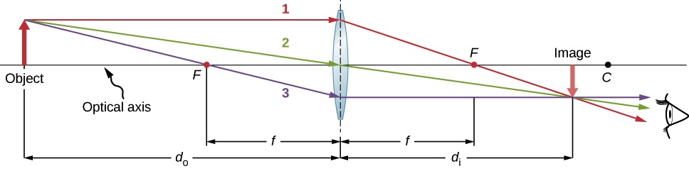

Figure 30.4The image is formed at the point of intersection of the refracted rays, or their extensions. If the refracted rays themselves intersect, the image can be projected on a screen, and it is a real image. A real image is formed in Figure 30.5(a). If the refracted rays have to be extended on the opposite side of the lens in order to find their point of intersection, the image cannot be projected on a screen and it is a virtual image. A virtual image is formed in Figure 30.5(b).

The equation that relates the object distance, image distance, and focal length is the same as the one used for spherical mirrors. Lateral magnification is also found the same way as for mirrors.
 Thin Lens Equation
 Lateral Magnification
The focal length of a thin lens is dependent upon the radius of curvature of the two sides of the lens and the index of refraction of the lens, and the substance surrounding the lens. For a thin lens in air, the focal length is found using the lens maker’s equation.
 Lens Makers Equation
In this equation
 is the index of refraction of the lens
 is the radius of curvature of the first refractive surface
 is the radius of curvature of the second refractive surface
The greater effect a lens has on light rays, the more powerful it is said to be. For example, a powerful converging lens will focus parallel light rays closer to itself and will have a smaller focal length than a weak lens. The power of a lens is defined to be the inverse of its focal length. In equation form, this is
 Optical Power
Power of a lens is measured in Diopters, D. Notice that D=1/m.
Sign Convention For Thin Lenses
The side of the lens where the first object is located is called the object side. The side opposite to that is called the image side.
- If an object is on the object side, do >0, and if it is on the image side, do<0.
- If an image is on the image side, di>0, and if it is on the object side, di<0.
- For a converging lens, f>0.
- For a diverging lens, f<0.
- If the center of curvature is on the image side, R>0, and if it is on the object side, R<0
Example 30.1
A biconvex lens with the index of refraction of 1.50 has a radius of curvature of 20.0cm on one side and 30.0cm on the other side. What is the focal length of this lens in the air, and what is its power?
Solution

We have to use the lens makers equation to determine the focal length. It doesn’t matter which side we place the object on. In the configuration shown in Figure 30.6, The center of curvature of the first refracting surface is on the image side, and R1>0, while the center of curvature of the second refracting surface is on the object side, and R2<0.
R1=20.0cm, and R2=-30.0cm


Notice that the focal length is positive, as is expected for a converging lens.
To find the power of the lens in Diopters, we need to make sure the focal length is in meters.


Example 30.2
Find the location, orientation, and height of the image for a 2.00cm high object at each of the following positions in front of a converging lens with a power of 25.0D. In each case, construct a ray diagram to scale to confirm your findings.
a) do=11.0cm
b) do=7.00cm
c) do=2.00cm
Solution to (a)
Let’s first find the focal length of the lens, keeping in mind that D=1/m, and that the power and focal length of a converging lens are positive.


Now we can use the thin lens equation to determine the location of the image.


Since di>0, the image is formed on the image side and it is real. The magnification is


Since M<0, the image is inverted. And since |M|<1, the image is reduced. To find the height of the image, use magnification


The ray diagram is consistent with the results:

Solution to (b)
Same approach as in (a)


Since di>0, the image is formed on the image side and it is real. The magnification is


Since M<0, the image is inverted. And since |M|>1, the image is magnified. To find the height of the image, use magnification


The ray diagram is:

Solution to (c)
Same approach as in (a)


Since di<0, the image is formed on the object side and it is virtual. The magnification is


Since M>0, the image is upright. And since |M|>1, the image is magnified. To find the height of the image, use magnification


The ray diagram is:

Discussion
A converging lens can form a real and a virtual image. The real image could be reduced or magnified. A virtual image is formed when do<f.
diverging (concave) lenses
Ray Diagram For A Diverging Lens
- A ray entering a diverging lens parallel to the optical axis exits along the line that passes through the focal point on the same side of the lens (ray 1 in Figure 30.10).
- A ray passing through the center of a diverging lens does not deviate (ray 2 in Figure 30.10).
- For a diverging lens, a ray that approaches along the line that passes through the focal point on the opposite side exits the lens parallel to the axis (ray 3 in Figure 30.10).

A diverging lens only forms a virtual image regardless of the distance between the object and the lens, as shown in Figure 30.10. Notice the differences between the virtual images formed by a converging lens and a diverging lens in Figure 30.11.

The lens makers equation, the thin lens equation, the magnification equation, and the sign convention for a diverging lens are all the same as the ones for a converging lens.
Example 30.3
A planoconcave lens with the index of refraction of 1.50 has a radius of curvature of 20.0cm on the curved side. What is the focal length of this lens in the air, and what is its power?
Solution

Once again, it doesn’t matter which side we place the object on when we use the lens makers equation. In the configuration shown in Figure 30.12, the first refracting surface is the flat side with a radius of curvature that approaches infinity, and the center of curvature of the second refracting surface is on the image side, and therefore positive.
R1→∞, and R2=+20.0cm


Notice that the focal length is negative, as it is expected for a converging lens.
To find the power of the lens in Diopters, we need to make sure the focal length is in meters.


Example 30.4
A diverging lens has a focal length of 4.00cm. Determine the location of the image and its characteristics if the object is located 6.00cm from the lens. Draw a ray diagram to scale to confirm your calculations.
Solution
Use the thin lens equation to locate the image. Notice that since this is a diverging lens, the focal length is negative.


Since di<0m, the image is formed on the object side and it is virtual. Now, let’s find the magnification.


Since M>0, the image is upright. And, since |M|<1, the image is reduced.
Here is the ray diagram.

Attribution
This chapter contains material taken from Openstax University Physics Volume 3-Geometric Optics and Image Formation, and is used under a CC BY 4.0 license. Download this books for free at Openstax
To see what was changed, refer to the List of Changes.
Problems
- [openstax univ. phys. vol.3 – 2.50] A flower is 75.0 cm away from the lens of a camera that has a focal length of 35.0mm. How far from the lens must the film in a camera be to photograph the flower?
- [openstax univ. phys. vol. 3 – 2.51] A certain slide projector has a lens with a focal length of 100 mm. A slide is placed 103 mm from the lens.
- How far away from the lens should the screen be placed to see a sharp image?
- If the slide is 24.0 mm by 36.0 mm, what are the dimensions of the image?
- [openstax univ. phys. vol. 3 – 2.52] A doctor examines a mole with a 15.0-cm focal length magnifying glass held 13.5 cm from the mole.
- Determine the location of the image.
- How big is the image of a 5.00 mm diameter mole?
- [openstax univ. phys. vol. 3 – 2.61(modified)] An object of height 3.00 cm is placed 5.00 cm in front of a converging lens of focal length 20.0 cm and observed from the other side of the lens.
- Where is the image formed?
- What is the height of the image?
- Draw a ray diagram to scale to verify your calculations.
- [openstax univ. phys. vol. 3 – 2.62(modified)] An object with a height of 3.00 cm is placed 5.00 cm in front of a diverging lens of focal length 20.0 cm and observed from the other side.
- Where is the image formed?
- What is the height of the image?
- Draw a ray diagram to scale to verify your calculations.
- A diverging lens is used to produce a virtual image of an object that is 1.50m in front of the lens. The image is 30.0cm from the lens.
- What is the focal length of the lens?
- What is the magnification of the image?
- An object is placed in front of a diverging lens with a focal length of 20.0cm. Find the location of the image and the image characteristics if the distance between the object and the lens is
- 10.0cm.
- 30.0cm.
- An object is placed in front of a converging lens with a focal length of 20.0cm. Find the location of the image and the image characteristics if the distance between the object and the lens is
- 10.0cm.
- Draw a ray diagram to scale to confirm your calculations in (a).
- 30.0cm.
- Draw a ray diagram to scale to confirm your calculations in (b).
- A plano-concave lens is made of glass with an index of refraction of 1.60. The radius of curvature of the concave surface is 30.0cm. What is the focal length of the lens?
- A meniscus-convex (Figure 30.1)lens is made of glass with an index of refraction of 1.50. The radius of curvature of one side is 4.00cm, and that of the other side is 3.00cm. What is the focal length of the lens?
- A plano-convex lens is made of glass with an index of refraction of 1.60. The radius of curvature of the convex surface is 5.00cm. What is the focal length of the lens?
