Dynamics – Forces and Motion
Last Update: 12/01/2022
the terminology used for some common forces
Weight
One force that always exists on any object we consider on the surface of the Earth is the gravitational force on the object by the Earth. Newton’s universal law of gravitation states that every particle in the universe attracts every other particle with a force along a line joining them. The force is directly proportional to the product of their masses and inversely proportional to the square of the distance between them. For two bodies having masses m1 and m2 with a distance r between their centers of mass, the equation for Newton’s universal law of gravitation is
 Newton’s Universal Law of Gravitation

The gravitational force between most objects is usually very small. For example, the gravitational force between two persons, each with a mass of 70kg (154lb) standing 1.0m apart is


This force is about 100,000 times smaller than the force needed to lift an ant!
Notice that the constant G is very small, and that’s why in most cases, the gravitational force comes out to be very small and not noticeable. But what if we calculate the force between a very massive object, like the planet Earth, and another object, such as a 70kg person who is standing on the surface of the Earth, so that the distance between them is equal to the radius of the Earth? Let’s see what we get.


Now, this is a large force! In fact, this is exactly the force we have to apply to lift a 70kg person. This gravitational force between the Earth and an object on the surface of the Earth is called weight.
Notice that to determine the weight of an object that has a mass of m and is on the surface of the Earth we need to determine the gravitational force between the Earth and that object by using the equation that represents the Newton’s Law of gravitation and using the mass of the Earth and the mass of the object for m1 and m2 and the radius of the Earth for r.


The constant is usually represented with g.  . Therefore

Now consider an object in free fall. The only force on this object is the Earth’s gravitational force which is the same thing as the object’s weight or mg. Using Newton’s Second Law we get


 Notice that since N=kgm/s2, N/kg=m/s2.
Now you can see why we used 9.8m/s2 as the value for acceleration during free fall. Also, since the value for g is obtained by using the radius of the Earth as the distance between the Earth and the object of interest, this value only represents the free-fall acceleration only when the object is close to the surface of the Earth. Similarly, m(9.8N/kg) can be used to calculate weight only when the object is on the surface of the Earth. In general, acceleration due to gravity g varies slightly over the surface of Earth with elevation. This means that the weight of an object depends on its location and is not an intrinsic property of the object. Weight varies dramatically if we leave Earth’s surface. On the Moon, for example, acceleration due to gravity is only 1.62m/s2. A 1.0-kg mass thus has a weight of 9.8 N on Earth and only about 1.6 N on the Moon.
The broadest definition of weight in this sense is that the weight of an object is the gravitational force on it from the nearest large body, such as the Earth, the Moon, or the Sun. This is the most common and useful definition of weight in physics.
With the exception of the gravitational force, almost all other forces we will discuss in physics-I are contact forces. This means that the force is the result of two objects coming in physical contact with one another.
Normal Force and Friction Force
When an object is in contact with a surface, the interaction between the object and the surface results in a force between them. The object applies a force on the surface and the surface applies an equal force on the object. If you place your hand on a table and push down, the table pushes back on your hand with an equal force. Clearly, if you push harder, the force on your hand increases. Try it! If you push your hand straight down on the table, the table pushes back in a direction perpendicular to the surface. But if you slide your hand gently forward along the surface of the table, you barely feel the table pushing upward. Instead, you feel the friction acting as a resistive force to the motion of your hand. This force acts parallel to the surface and opposite to the motion of your hand. If you push down with your hand and also push forward, you feel both the upward force on your hand and the resistive force parallel to the surface as shown in Figure 8.1.

In Figure 8.1 the force that the table applies to the hand is  . The component of this force that is perpendicular to the surface of the table
  is called the normal force (or support force), and the component that is parallel to the surface and opposes the motion
  is called the friction force.
Now consider a skier on a slope as shown in Figure 8.2. The skier is interacting with only two objects, the Earth and the slope. The force on the skier by the Earth is the gravitational force (weight), represented with W in the diagram. Also shown on the diagram are the components of W parallel and perpendicular to the surface,  and
and  respectively. The force on the skier by the slope is not shown on the diagram. Instead, the components of it parallel to the surface, the friction force (f), and perpendicular to the surface, the normal force (N) are shown.

Notice that the normal force doesn’t have to be vertical or even have a component in the vertical direction. In the picture of the man leaning against the wall, the normal forces (support forces) are shown. Two of them are vertical and are applied by the ground to his feet, and one normal force is horizontal and it is applied by the wall on the man’s back.

Another example of a horizontal normal force is the force applied by the headrest of a car seat. The headrest provides a normal force on your head so that the head accelerates along with the body, keeping your head above your shoulders and your neck in a safe position. The normal force applied by a headrest is particularly essential in case the vehicle is hit from behind. The collision causes the vehicle to suddenly accelerate forward. The body of the person sitting in the car also accelerates forward due to the force applied by the back of the seat. But without a headrest, the head stays behind (this is inertia) and this can cause whiplash. You can see the importance of a proper headrest in these crash-test videos:
The size of the normal force on an object depends on how hard that object is pushing against the surface. For example, when a person stands still on flat ground, they are in static equilibrium and the normal force pushing up from the ground is equal to their weight. In order to jump, the muscles of the leg contract to push down against the floor. This downward push results in an equal reactive normal force from the floor, so that now the normal force is greater than body weight and there is an upward net force. Now with an upward net force, the body will experience an upward acceleration. The following graph of the normal force on a person was created by jumping and landing on a force plate, which is essentially an extra-tough digital scale that records the normal force that it provides over time.

Tension Force
When an object is connected to a flexible medium, the interaction between the object and the flexible medium results in a force between them. A flexible medium could be anything like a rope, chain, wire, cable, string, or tendons attached to muscles. The force that this flexible medium applies to the object is called the tension force. The tension force is always along the length of the flexible medium. In Figure 8.3, the mass, m, is interacting with two objects – the Earth, and the rope. The force on the mass by the Earth is the gravitational force (weight) represented with W, and the force on the mass by the rope is the tension force that is pulling up on the mass and is represented with T. The hand pulling on the rope is also interacting with the rope. The force on the hand by the rope is also the tension force shown as the force T pulling down on the hand. Notice that as long as the gravitational force on the flexible medium, in this case, the rope, is negligible and the rope is not interrupted by another object, the tension force is the same all along its length. So, in Figure 8.3, the tension force pulling up on the mass has the same magnitude as the tension force pulling down on the hand. In this book, unless specifically stated otherwise, we will assume the gravitational force on all flexible media (rope, string, cord, etc.) is negligible.
 |
Similarly, in Figure 8.4, The tension force pulling up on the baby is the same size as the tension force pulling down on the scale (T1), and the tension force pulling up on the scale is equal in magnitude to the tension force pulling down on the ceiling (T2).

Elastic Force (Restoring Force)
As the name implies, the elastic force is a force applied by something elastic, like a rubber band, or a spring. If you have ever played with a rubber band or spring, you have probably noticed that at first, it doesn’t take much force to stretch it a little bit, but as you stretch it, it takes more force to stretch it even more. This is because the force applied by the elastic material to your hand becomes larger as the elastic material is stretched. In fact, as long as you are not stretching the elastic material so much as to deform it, the force applied by the elastic material to your hand is directly proportional to how far you have stretched it from its equilibrium length. This is known as Hooke’s Law. We are going to use spring as a representation of an elastic material, simply because it is easier to draw diagrams and visualize the situation with a spring.
 Hooke’s Law
In the equation above, Fspring is the force applied by the spring, x is how far the spring has been stretched or compressed from its equilibrium length, and K is the spring constant. Spring constant is a measure of the stiffness of a spring. The higher the spring constant, the more force it takes to stretch the spring by a given amount. For example, a spring with a spring constant of 200N/m requires 200N of force to stretch it 1m. The negative sign in the equation is due to the fact that the direction of the force is always opposite to the direction the spring has been stretched or compressed. As shown in Figure 8.5, the hand is stretching the spring to the right, and the force applied by the spring on the hand is to the left.

free body diagram
The first step in analyzing the state of motion of an object or a system of objects is to draw a free-body diagram. In a free-body diagram, we show all the external forces that are acting on the object or on the system. In this, and the next few chapters (anything discussed before introducing rotation) we will treat the object or the system of interest as a point mass. In other words, we assume the whole object or the system can be represented as a single point and that all the mass is concentrated at that point.
Example 8.1
Figure 8.2 shows the free body diagram for the skier. Notice that the skier is represented with a dot and only the forces that are acting on the skier are shown on the free-body diagram. For each force that we draw on the free-body diagram, we must be able to identify the object that is applying the force. In the case of the skier, the interaction between the skier and the Earth results in the gravitational force (weight), W. Therefore W is applied by the Earth. Similarly, the normal force, N, and the friction force, f, are the result of the interaction between the skier and the slope. Therefore, N and f are applied by the slope.
Figure 8.3, and Figure 8.4 are not free-body diagrams because each figure shows forces acting on multiple objects.
Figure 8.1 is not a free-body diagram either because it doesn’t show all the forces acting on the hand. A free-body diagram of the hand would be as it is shown below in Figure 8.6.

is the force on the hand by the table,  is the gravitational force applied by the Earth, and
  is the force applied by the forearm on the hand.
Figure 8.7 shows the free-body diagram for a traffic light. T1 and T2 are tension forces applied by the wires and W is the gravitational force applied by the Earth.

In Figure 8.8(a) the boy and the wagon together form the system of interest. In other words, we treat the boy and the wagon as one entity represented by a point mass. The free-body diagram on the right of the picture shows all the external forces acting on this system. Notice that we don’t include internal forces that are due to the interaction between the boy and the wagon on the free-body diagram. The free-body diagram shows the following forces:
Normal force, N, and friction force, f applied by the ground
Gravitational force (weight), W, applied by the Earth
Force F1, applied by one child pushing the wagon
Force F2, applied by the other child pushing the boy in the wagon
Figure 8.8(c) also shows the free-body diagram for the boy-wagon system in a slightly different situation.

Figure 8.9(c) is the free-body diagram of a block attached to a vertical spring. Notice that the magnitude of the force applied by the spring is proportional to how far the spring has been stretched.

Video Example – Drawing Free Body Diagrams
steps in problem-solving
Newton’s Second Law is

Since each vector can be written as the vector sum of its components, we can rewrite Newton’s Second Law for a two-dimensional situation as:

This results in two separate equations that show Newton’s Second Law in component form:


The following are the steps in solving problems where we have to apply Newton’s Second Law.
Step 1 – Identify the object or the system of interest and draw a free-body diagram for it.
Step 2 – Identify the direction of acceleration and pick a coordinate system with one axis parallel to the direction of acceleration. Indicate which direction along each axis is the positive direction.
Step 3 – Using the coordinate system above, break up all the forces on the free-body diagram into their components. Draw these components and calculate them.
Step 4 – Apply Newton’s Second Law in component form along with other relevant equations.
Step 5 – Solve the resulting system of equations.
Example 8.2 – Different Tensions at Different Angles
Consider the traffic light (mass 15.0 kg) suspended from two wires as shown in Figure 8.10. Find the tension in each wire, neglecting the masses of the wires.

Solution
Step 1 – The system of interest is the traffic light, and its free-body diagram is shown in Figure 8.10. The three forces involved are the tension forces T1 and T2 by the wires and the gravitational force, W, by Earth.
Step 2 – The traffic light is not accelerating, so we can use the conventional x-y coordinate system, with the x-axis horizontal and the y-axis vertical. We take to the right, along the x-axis, and up along the y-axis to be the positive directions.
Step 3 – The components of the two tension forces are shown in Figure 8.10. Let’s express these components in terms of the magnitude of the tension forces and the angle they make with the x-axis.

|

|

|

|


Step 4 –Since the traffic light is at equilibrium, its acceleration is zero. Also, note that w=mg.
In the x-direction:


In the y-direction:

Step 5 – We have a system of equations-two equations and two unknowns. We can use the method of elimination to solve for the unknowns.


Discussion
Both tensions would be larger if both wires were more horizontal, and they will be equal if and only if the angles on either side are the same.
Video Example – Sliding a box on a level surface by pushing down on it at an angle
Example 8.3
Figure 8.11 shows a 75.0-kg man (weight of about 165 lb) standing on a bathroom scale in an elevator. Calculate the scale reading:
a) if the elevator accelerates upward at a rate of 1.20 m/s2.
b) if the elevator moves upward at a constant speed of 1 m/s.

Solution for (a):
Step 1 – The system of interest is the man. The free-body diagram is shown in Figure 8.11. The two forces are the normal force, Fs, applied by the scale, and the gravitational force (weight), W, applied by the Earth.
Step 2 – The man is accelerating upward. Therefore we pick a coordinate system with one axis vertical, parallel to the acceleration, and the other axis horizontal. We take “up” along the y-axis to be the positive direction.
Step 3 – Since the two forces are along the y-axis, there is no component to draw or to calculate.
Step 4 and Step 5 – There is no equation to write for the x-direction. Newton’s Second Law applied in the y-direction yields:


Discussion
So, the scale reading in the elevator is greater than the person’s weight of 735-N (165 lb) weight. This means that the scale is pushing up on the person with a force greater than his weight, as it must in order to accelerate him upward. Clearly, the greater the acceleration of the elevator, the greater the scale reading, consistent with what you feel in rapidly accelerating versus slowly accelerating elevators.
This solution also applies to an elevator accelerating downward. When an elevator accelerates downward, a is negative (since we took “up” to be the positive direction), and the scale reading becomes less than the weight of the person. If the elevator is in free-fall and accelerating downward at g, then the scale reading will be zero and the person will feel weightless.
Solution for (b):
The approach is similar to what we did for (a), except that in this case, the acceleration is zero. Therefore


Discussion
The scale reading is 735 N, which equals the person’s weight. This will be the case whenever the elevator has a constant velocity—moving up, moving down, or stationary.
Video Example – Block sliding down on an incline
Example 8.4- Sliding Down An Incline
Consider the skier on a slope shown in Figure 8.2. Her mass including equipment is 60.0 kg. What is her acceleration if friction is known to be 45.0 N?
Step 1 – The system of interest is the skier and all her equipment. The free-body diagram is shown in Figure 8.2. The forces are the normal force, N, and the friction force, f, applied by the slope, and the gravitational force, W, applied by the Earth.
Step 2 – The skier is accelerating down the slope. So we pick the x-axis along the slope, parallel to acceleration, and the y-axis perpendicular to it. We take down the slope to be the positive direction for the x-axis and up in the direction of the normal force to be the positive direction along the y-axis.
Step 3 – The normal force, N, is already along the y-axis, and the friction force, f, is along the x-axis, therefore there is no component to draw or calculate for them. The gravitational force (weight), W, is broken up into its components, along the x-axis, and along the y-axis. Let’s calculate these components.
|
|
|


Step 4 and Step 5 – In the x-direction:


Video Example – The Atwood machine: Two blocks connected with a rope that goes over a pulley
Attributions
This chapter contains material taken from MIT Open Courseware, Physics, Classical Mechanics, Chapter 8.3, and is used under a CC BY NC SA 4.0 license, and Openstax College Physics-Dynamics: Force and Newton’s Laws of Motion by Openstax and is used under a CC BY 4.0 license. Download this book for free at Openstax-College Physics
The graph of Normal Force in a Jump and the paragraph above it are taken from Body Physics: Motion to Metabolism by Lawrence Davis is licensed under a Creative Commons Attribution-NonCommercial-ShareAlike 4.0 International License
To see what was changed, refer to the List of Changes.
problems
- [openstax univ. phys. vol. 1 – 13.20] Calculate Earth’s mass given the acceleration due to gravity at the North Pole is measured to be 9.832m/s2 and the radius of the Earth at the pole is 6356 km, and compare this with NASA’s Earth Fact Sheet value of 5.9726×1024kg.
- [openstax univ. phys. vol. 1 – 13.23 – modified] The mass of a particle is 15.0 kg.
- What is its weight on Earth?
- The acceleration due to gravity on the Moon is 1.62m/s2. What is its weight on the Moon?
- What is its mass on the Moon?
- What is its weight in outer space far from any celestial body?
- What is its mass at this point?
- If it takes 30.0N on Earth to bring this object to a stop from a velocity of 10.0m/s in 5.00s, how much force does it take to stop it from the same velocity and in the same amount of time on the Moon? in outer space?
- In each case, find the normal force on the 10.0kg block.
- The block is at rest on a horizontal table.
- The block is sliding down a ramp that makes a 25.0° angle with the horizontal.
- The block is accelerating on a frictionless horizontal surface at a rate of 1.75m/s2 as it is being pulled by a rope that makes a 40.0° angle above the horizontal.
- The block is accelerating on a frictionless horizontal floor at a rate of 1.75m/s2 as a person pushes it with a force that makes a 40.0° angle below the horizontal.
- The block is at rest while it is being pushed against a frictionless wall with a force that makes a 60.0°angle above the horizontal.
- A 15.0kg block is on a frictionless horizontal surface when two forces F1 and F2 act on it. Find the acceleration of the block if F1 =30.0N and is horizontal, in the positive x-direction, while F2=40.0N @ -20°?
- [openstax univ. phys. vol. 1 – 5.60] Suppose a 60.0-kg gymnast, climbs a rope.
- What is the tension in the rope if he climbs at a constant speed?
- What is the tension in the rope if he accelerates upward at a rate of 1.50m/s2?
- [openstax univ. phys. vol. 1 – 5.67] A 2.00-kg block is on a perfectly smooth ramp that makes an angle of 30.0º with the horizontal.
- What are the block’s acceleration down the ramp and the force of the ramp on the block?
- What force must be applied to the block to allow it to slide down the ramp with constant velocity?
- A force F=10.0N acts on two blocks m1=2.00kg and m2=3.00kg that are on a frictionless horizontal surface.
- Find the acceleration of the blocks.
- Find the force between the two blocks.

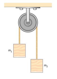
- Two blocks m1=4.00kg and m2=5.00kg are connected with a rope that goes over a pulley. Find the acceleration of the blocks and the tension in the rope.
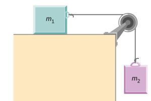
- Two blocks m1=6.00kg and m2 are connected with a rope that goes over a pulley. Find m2 If m1 that is placed on a horizontal, frictionless table accelerates at a rate of 0.500m/s2.
- When a 2.00kg object is attached to a vertical spring, the spring stretches by 3.00cm. Find the spring constant of the spring.
- [openstax univ. phys. vol. 1 – 5.88] As shown below a 30.0kg block is resting on a frictionless ramp inclined at 60.0° to the horizontal. the block is held by a spring that is stretched 5.00cm. Find the spring constant of the spring.


