Electric Charges In Motion
Last Update: 05/29/2020
Electric Current
Electric current is defined to be the rate at which charge flows. Electric current is represented with “I” and measured in Ampere(Amp).
 Electric Current

Example 24.1
(a) What is the current involved when a truck battery sets in motion 720 C of charge in 4.00 s while starting an engine?
(b) How long does it take 1.00 C of charge to flow through a handheld calculator if a 0.300-mA current is flowing?
(c) With a current of 0.300mA in a calculator, how many electrons pass a point in the circuit per second?
Solution for (a)
We can use the definition of current to answer this question.


Solution for (b)
Using the same approach we get


Solution for (c)
The rate of flow of charge in the circuit is 0.300 mA, which is the same thing as 0.300×10⁻³A or 0.300×10⁻³C/s. Since the charge of an electron is 1.60×10⁻¹⁹C, we can determine the number of electrons per second.


Notice that the number of electrons that pass a point in the circuit, even when the current is so incredibly small, is huge!
In a metal wire, the current is carried by electrons, and as we know, electrons have a negative charge. By convention, however, we take the direction of current to be the direction that positive charges flow in the circuit, which is simply the opposite to the direction the electrons move. So, from now on, we may talk about positive charges moving in the wires when we discuss circuits, but keep in mind, that in reality, the current-carrying particles are electrons, and electrons have a negative charge.
We defined current as the rate of flow of charge. This is not the same thing as the speed. To see the difference consider the currents in the two wires shown in Figure 24.1. In both wires, charges have the same speed. But in the wire at the top, more charges pass a certain point per unit time. Therefore, the current in the top wire is larger than the current in the bottom one.

Good conductors have large numbers of free charges in them. In metals, the free charges are free electrons. Figure 24.2 shows how free electrons move through an ordinary conductor. The distance that an individual electron can move between collisions with atoms or other electrons is quite small. The electron paths thus appear nearly random, like the motion of atoms in a gas. That’s why we need to think of electrons drifting in the wire.

We can obtain an expression for the relationship between current and drift speed by considering the number of free charges in a segment of wire, as illustrated in Figure 24.3.

The number of free charges per unit volume is given the symbol n and depends on the material. The shaded segment has a volume Ax so that the number of free charges in it is nAx. The charge ΔQ in this segment is thus qnAx, where q is the amount of charge on each carrier. For electrons, q=1.60×10⁻¹⁹C. Current is charge moved per unit time; thus, if all the original charges move out of this segment in time Δt, the current is

Note that  is the magnitude of the drift speed, vd, since the charges move an average distance x in a time Δt. Rearranging terms gives
 Current In Terms Of Drift Speed
In this equation
 is the number of free charges per unit volume
 is the charge of one charge carrier
 is the cross-sectional area of the wire
 is the drift speed of charges
Example 24.2
Calculate the drift velocity of electrons in a 12-gauge copper wire (which has a diameter of 2.053 mm) carrying a 20.0-A current, given that there is one free electron per copper atom. (Household wiring often contains 12-gauge copper wire, and the maximum current allowed in such wire is usually 20 A.) The density of copper is 8.80×10³kg/m3.
Solution
We need to find n, the number of free charges per unit volume. Since there is one electron per atom, we need to find the number of atoms per volume. The density gives us mass per unit volume. So we need to find the mass of one atom to find out how many atoms exist per unit volume.
From the periodic table, we get the molar mass of copper to be 63.546.

This means the mass of 1mol of copper is 63.546g.

Now we can use density to find the number of atoms per volume.

The cross sectional area of the wire, A, is


Now we can find the drift speed by using


Discussion
Notice that this is a very small speed and it indicates how fast electrons drift in the wire. The actual speed of electrons is in fact extremely large, but due to their random motion, their drift speed is quite small.
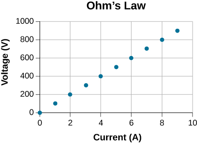
ohm’s law
In order to establish a current in a wire, there must be a voltage. As we saw in UNIT 22, voltage is the difference in potential, which is similar to the difference in elevation in a gravitational field. If a ball is placed in a region where there is a difference in elevation (like the side of a hill), the ball rolls down. Similarly, when electric charges are in a region where there is a difference in potential, they move and establish a current. In a simple circuit, the device that creates a difference in potential and drives the current is a battery. For many devices, including all wires and metals in general, the size of the current is directly proportional to voltage.

Another factor that affects the size of the current is electrical resistance. Atoms in a metallic conductor are packed in the form of a lattice structure. Some electrons are far enough away from the atomic nuclei that they do not experience the attraction of the nuclei as much as the inner electrons do. These are the free electrons. They are not bound to a single atom but can instead move freely among the atoms in a “sea” of electrons. These free electrons respond by accelerating when a voltage is applied but their motion is not completely free because they collide with the atoms in the lattice and other electrons along their way. This resistance exhibited by the conductor against the flow of electrons is what we call electrical resistance. Resistance is represented with R and measured in Ohm(Ω). The size of the current in a conductor is inversely proportional to resistance.

We can write these two relationships in the form of an equation that is known as Ohm’s Law.
 Ohm’s Law
It is important to note that even though this equation is known as Ohm’s Law, it really doesn’t represent a “law” of nature. In other words, the equation above does not apply to all devices. For example, things like diodes, LEDs, and transistors do not behave as described by Ohm’s Law equation. We often refer to devices that do obey Ohm’s Law as ohmic. In this book, we will only discuss ohmic devices.
Note the relationship between the units

The resistance of an object depends on its shape and the material of which it is composed. The cylindrical resistor in Figure 24.5 is easy to analyze, and, by so doing, we can gain insight into the resistance of more complicated shapes. As you might expect, the cylinder’s electric resistance, R, is directly proportional to its length, L, similar to the resistance of a pipe to fluid flow. The longer the cylinder, the more collisions charges will make with its atoms. The greater the diameter of the cylinder, the more current it can carry (again similar to the flow of fluid through a pipe). In fact, R is inversely proportional to the cylinder’s cross-sectional area, A.

For a given shape, the resistance depends on the material of which the object is composed. Different materials offer different resistance to the flow of charge. We define the resistivity, ρ, of a substance so that the resistance, R, of an object is directly proportional to ρ. Resistivity, ρ, is an intrinsic property of a material, independent of its shape or size. The resistance, R, of a uniform cylinder of length, L, of cross-sectional area, A, and made of a material with resistivity, ρ, is
 Resistance Of A Conductor
Table 24.1 gives representative values of ρ. The materials listed in the table are separated into categories of conductors, semiconductors, and insulators, based on broad groupings of resistivities. Conductors have the smallest resistivities, and insulators have the largest; semiconductors have intermediate resistivities. Conductors have varying but large free charge densities, whereas most charges in insulators are bound to atoms and are not free to move. Semiconductors are intermediate, having far fewer free charges than conductors, but having properties that make the number of free charges depend strongly on the type and amount of impurities in the semiconductor.

Example24.3
a) What is the resistance of an automobile headlight through which 2.50 A flows when 12.0 V is applied to it?
b) If the headlight filament is made of tungsten, and is in the shape of a cylinder 4.00 cm long (it may be coiled to save space), what is its diameter?
Solution for (a)
We can use Ohm’s Law.


Solution for (b)
We can look up the resistivity of tungsten in Table 24.1. Using the relationship between resistance and resistivity we can determine the cross-sectional area of the wire, and from that its diameter.
ρtungsten = 5.6×10⁻⁸Ωm


The cross-sectional area of a wire is a circle.


So the diameter of the wire is


The resistivity of some materials has a strong temperature dependence. In some materials, such as copper, the resistivity increases with increasing temperature. In fact, in most conducting metals, the resistivity increases with increasing temperature. The increasing temperature causes increased vibrations of the atoms in the lattice structure of the metals, which impede the motion of the electrons. In other materials, such as carbon, the resistivity decreases with increasing temperature. In many materials, the dependence is approximately linear and can be expressed as follows:
![\boxed{\rho=\rho_0[1+\alpha (T-T_0)]}](https://pressbooks.pub/app/uploads/quicklatex/quicklatex.com-89030828629a0f1b10b2849c3374cade_l3.png "Rendered by QuickLaTeX.com") Temperature Dependence of Resistivity
Temperature Dependence of Resistivity
 is the resistivity of the material at temperature T
 is the temperature coefficient of resistivity of the material
 is the resistivity at T0, usually taken as 20.0ºC.

Note also that the temperature coefficient of resistivity, , is negative for the semiconductors listed in Table 24.2, meaning that their resistivity decreases with increasing temperature. They become better conductors at higher temperatures because increased thermal agitation increases the number of free charges available to carry current.
Example 24.4
A tungsten filament at 20.0ºC has a resistance of 0.350Ω. What would the resistance be if the temperature is increased to 2850ºC?
Solution
Assuming no significant change in the dimensions of the wire, we can see that an increase in temperature causes an increase in resistance that can be determined as follows.
and ![\rho=\rho_0[1+\alpha (T-T_0)]](https://pressbooks.pub/app/uploads/quicklatex/quicklatex.com-708631f38e8842364f0c03eacaddb48f_l3.png "Rendered by QuickLaTeX.com") result in
result in
![R=\rho_0[1+\alpha (T-T_0)] \frac{L}{A}](https://pressbooks.pub/app/uploads/quicklatex/quicklatex.com-0185b8dfebb7a285c4737e9ff57b415d_l3.png "Rendered by QuickLaTeX.com")
![R=\rho_0 \frac{L}{A} + \rho_0 \alpha (T-T_0)] \frac{L}{A}](https://pressbooks.pub/app/uploads/quicklatex/quicklatex.com-fa16cd3bd3b5b6cbc60fc53f94459e10_l3.png "Rendered by QuickLaTeX.com")

![R=R_0 [1+\alpha (T-T_0)]](https://pressbooks.pub/app/uploads/quicklatex/quicklatex.com-d58ebe9d632d4e2b4731157d6d164c61_l3.png "Rendered by QuickLaTeX.com")
![R=0.350\Omega [1+4.5\times 10^{-3}\frac{1}{^\circ C} (2850^\circ C-20.0^\circ C)]](https://pressbooks.pub/app/uploads/quicklatex/quicklatex.com-a177bc3a0ce3ccadf4163449ce665437_l3.png "Rendered by QuickLaTeX.com")

Discussion
Notice that the resistance changes by more than a factor of 10 as the filament warms to the high temperature and the current through the filament depends on the resistance of the filament and the voltage applied. If the filament is used in an incandescent light bulb, the initial current through the filament when the bulb is first energized will be higher than the current after the filament reaches the operating temperature.
Do Volts or Amps Kill you? Watch this video to find out.
power in electric circuits
Power is the rate at which work is done or energy is changed. In an electric circuit, positive charges move from high potential to low potential to establish a current. Since charges move through a difference in potential, their potential energy changes. The rate at which this potential energy changes is the electrical power of the circuit.


Since current is the rate of flow of charge, or
 Electric Power
The equation above is general and applies to all electrical devices under all conditions. Power is measured in watts (1W=1J/s).
In an ohmic device, Ohm’s Law can also be used to relate current and voltage. Using Ohm’s Law along with the general equation for power, we can express power in terms of current and resistance, or resistance and voltage.
AND  Resulting In
 AND Resulting In
Therefore:
 Power For An Ohmic Device
Example 24.5
Some makes of older cars have 6.00-V electrical systems.
(a) What is the resistance of a 30.0-W headlight in such a car?
(b) What current flows through it?
Solution for (a)
Since this is an ohmic device, we can use


Solution for (b)
We can either use Ohm’s Law or the general equation for power to determine the current.


In a simple circuit like the one in Figure 24.6, a resistor is connected to a battery. The function of the battery is to establish a voltage (difference in potential). The wires and the resistor are all made of conducting materials and have free charges. The battery does work and puts the positive charges at a high potential (positive terminal). This causes the positive charges to start drifting toward low potential (negative terminal) and a current is established. Wires have negligible resistance, but the resistor has significant resistance. This means that there are a lot of collisions between the charges that make up the current and the rest of the atoms in the resistor. As charges go from high to low potential and collide with the rest of the atoms in the resistor, they lose their potential energy. This energy is dissipated in the resistor in the form of thermal energy. For example, in the case of an incandescent light bulb, the energy dissipated in the filament makes the filament glow, as shown in Figure 24.7.
 |
 |
When the positive charges reach the negative terminal of the battery, the battery does work on these charges and transfers them from low to high potential. This increases the potential energy of the charges and the process continues.
It’s important to note that
- A circuit does not need a “source of charge”. Free charges that can move around and create a current already exist everywhere in the conductors.
- The battery is a source of energy in the circuit. The battery maintains a constant difference in potential across its terminals. This is done by doing work on the positive charges and transferring them from low to high potential.
- Electric energy is dissipated in a resistor in the form of thermal energy. The power of an ohmic device indicates how fast energy is dissipated in that device. For example, in the case of incandescent light bulbs, the power of the bulb is an indication of how bright it is. A 100W light bulb is brighter than a 40W bulb because more electrical energy is dissipated in the filament per unit time.
Attribution
This chapter contains material taken from Openstax College Physics -Electric Current, Resistance, and Ohm’s Law, and is used under a CC BY 4.0 license. Download these books for free at Openstax
To see what was changed, refer to the List of Changes.
problems
- [openstax univ. phys. vol. 2 – 9.23] How many electrons flow through a point in a wire in 3.00 s if there is a constant current of 4.00A?
- [openstax univ. phys. vol. 2 – 9.33] The current supplied to an air conditioner unit is 4.00 amps. The air conditioner is wired using a 10-gauge (diameter 2.588 mm) wire. The charge density is 8.48×1028electrons/m3. Determine the drift speed of the charges in the wire.
- [openstax univ. phys. vol. 2 – 9.39] The 0.100-mm-diameter tungsten filament in a light bulb has a resistance of 0.200Ω at 20.0ºC. What is the length of the wire?
- [openstax univ. phys. vol. 2 – 9.41] Find the ratio of the diameter of aluminum to copper wire, if they have the same resistance per unit length (as they might in household wiring).
- [openstax univ. phys. vol.2 – 9.51] A resistor rated at 250kΩ is connected across two D cell batteries (each 1.50 V) in series, with a total voltage of 3.00 V. The manufacturer advertises that their resistors are within 5% of the rated value. What are the possible minimum current and maximum current through the resistor?
- [openstax univ. phys. vol. 2 – 9.53] A resistor is placed in a circuit with an adjustable voltage source. The voltage across and the current through the resistor plotted as shown. Use the graph to determine the resistance of the resistor.
- [openstax univ. phys. vol. 2 – 9.59] The power dissipated by a resistor with a resistance of 100Ω is 2.00W. What is the current through the resistor and the voltage drop across the resistor?
- [openstax univ. phys. vol. 2 – 9.56] What is the maximum voltage that can be applied to a 20.0kΩ resistor rated at 0.250W?
- [openstax univ. phys. vol. 2 – 9.57] A heater is being designed that uses a coil of 14-gauge (diameter of 1.628mm) nichrome wire to generate 300 W of power using a voltage of 110V. What length of wire should be used?
- [openstax univ. phys. vol. 2 – 9.58(modified)] A 100-W incandescent bulb can be replaced by a single 16W LED bulb. Both produce 1600 lumens of light. Assuming the cost of electricity is $0.10 per kilowatt-hour, how much does it cost to use each bulb for four hours a day for one year?
- [openstax univ. phys. vol. 2 – 9.55] A 20.0V battery is used to supply current to a 10.0kΩ resistor. Assume the voltage drop across any wires used for connections is negligible.
- What is the current through the resistor?
- What is the power dissipated by the resistor?
- What is the power delivered by the battery?
- What happens to the energy dissipated by the resistor?

